Asterion DC Multioutput ASA Series Operational Manual
M330516-01
3-71
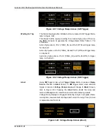
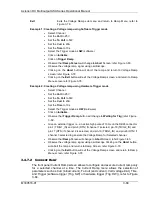
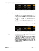
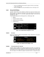
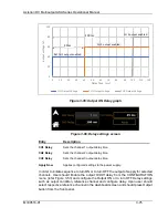
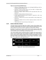
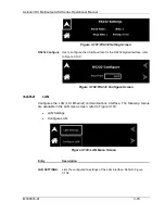
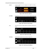
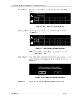
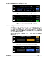
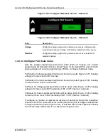
Figure 3-88: Current Ramp-Screen (Abort)
Exit
Exits the Current Ramp screen and return to Ramp Menu Screen, refer to
Example 1:
Creating a Current ramp using Software Trigger mode
•
Select channel
•
Set the
Curr
to 10A
•
Set the
To Curr
to 30A
•
Set the
Volt
to 25V
•
Set the
Time
to 10s
•
Connect an appropriate load to the supply
•
Select the Trigger mode as
SW
(software)
•
Click on
Initialize
•
Click on
Trigger Ramp
•
Observe that
Ramp
Screen Proceed to
Abort
Screen
; refer Figure 3-88.
•
Observe the current ramp signal using oscilloscope
•
Clicking on the
Abort
button will abort the ramp and returns to Current Ramp
screen; refer Figure 3-84
•
Clicking on the
Exit
button will exit the Ramp Menu screen; refer Figure 3-78.
Example 2:
Creating a Current ramp using Hardware Trigger mode
•
Select
channel
•
Set the
Curr
to 10A
•
Set the
To Curr
to 30A
•
Set the
Volt
to 25V
•
Set the
Time
to 10s
•
Connect an appropriate load to the supply
•
Select the Trigger mode as
HW
(Hardware)
•
Click on
Initialize
•
Observe that
Trigger Ramp
button will change to
Waiting for Trig
•
Give an external trigger i.e., an active high pulse of 10ms on the DB26 connector
pin-1 (TRIG1_IN) and pin-8 (RTN) if channel 1 selected, pin-10 (TRIG2_IN) and
pin-17 (RTN) if channel 2 is selected, and pin-19 (TRIG3_IN) and pin-26 (RTN) if
channel 3 selected to generate the Current Ramp for Selected channel.
•
Observe that
Ramp
screen
proceed to
Abort
Screen.
•
Observe the current ramp signal using oscilloscope.

