Asterion DC Multioutput ASA Series Operational Manual
M330516-01
1-10
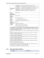
DC Regulation Characteristics- Constant Voltage Mode
Maximum line regulation
+/- 0.01% of rated voltage
Maximum load regulation
+/- 0.02% of rated voltage
Temperature Drift
+/- 100 PPM / degree Celsius
Stability
+/- 0.05% of rated voltage
DC Regulation Characteristics- Constant Current Mode
Maximum line regulation
+/- 0.05% of rated current
Maximum load regulation
+/- 0.15% of rated current
Temperature Drift
+/- 100 PPM / degree Celsius
Stability
+/- 0.05% of rated current
DC Regulation Characteristics- Constant Power Mode
Maximum line regulation
+/- 0.1% of rated power
Temperature Drift
+/- 100 PPM / degree Celsius
Stability
+/- 0.05% of rated power
1)
Output voltage accuracy, regulation and stability specifications are valid at the point
where the remote sense leads are connected. In the unit remote sense mode to be
selected using front panel or the digital interface.
2)
Regulation is measured with all the three channels to the rated power
1.2.6
Output Ripple, Noise and Transient Specifications
Rated
Output
Voltage (V)
Voltage
Ripple &
Noise RMS,
mV
(1)
Voltage
Ripple &
Noise PK-
PK, mV
(2)
Voltage &
Current
Rise Time
(ms), Full
load
(3)
Voltage &
Current Fall
Time (ms),
Full load
(4)
Voltage Fall
Time (ms),
No load
(5)
Transient
response
(ms
)
(6)
60
12
75
20
50
1500
1
80
15
90
25
60
2600
1
200
40
150
75
150
3500
2
400
80
300
100
200
4600
2
1)
RMS ripple/noise, over 20 Hz to 300 kHz bandwidth, is measured directly across the output terminals
with the supply operating into 90% of rated resistive load in all channels and nominal AC input line
voltage.
2)
PK-PK ripple/noise, over 20 Hz to 20 MHz bandwidth with the supply operating into 90% of rated
resistive load in all channels and nominal AC input line voltage.
3)
Maximum time, from 0%-100% of programming change from zero to rated output voltage with rated
resistive load.
4)
Maximum time, from 100%-0% of programming change from rated output voltage to zero with rated
resistive load.
5)
Maximum time, from 100%-0% of programming change from rated output voltage to zero with No load
6)
Typical time to recover within 0.5% of rated output voltage for load step of 10-90% of rated output
current. Transient response is measured with load change on one channel and two channels are loaded
to 90% of the rated power.

