Asterion DC Multioutput ASA Series Operational Manual
M330516-01
1-14
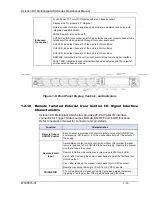
Enhanced
Front panel
Touch-Panel, TFT color LCD display with menu-based control;
D
isplay size: 1U models, 3.9” diagonal
Rotary encoder for menu navigation and parameter adjustment and entry, with
integrated selection switch.
POWER switch: turns unit on/off.
OUTPUT switch: turns output on/off of the selected channel. Output channel to be
turned on/off could be selected through front panel dashboard.
CH1 LED; indicates Channel-1 of the unit is in ON condition
CH2 LED; indicates Channel-2 of the unit is in ON condition
CH3 LED; indicates Channel-3 of the unit is in ON condition
REM LED: Indicates that the unit is under control of the remote digital interface,
FAULT LED: indicates that an internal fault has been detected and the output of
all channels has been shut down.
Figure 1-8: Front Panel Display, Controls, and indicators
1.2.10
Remote Isolated External User Control I/O Signal Interface
Characteristics
Asterion DC Multioutput ASA Series provides 26-Pin Digital I/O interface
connector for Trigger, Status output, Remote ON/OFF and Inhibit functions.
Refer to operation manual for connector and pin details.
Function
Characteristics
Remote Output
ON/OFF Control
Each channel is provided with control inputs to turn output ON/OFF the
power supply. DC Input (+) 2.7V-24V will enable (turn-on) the output of
the supply.
Remote Inhibit
Input
Switch/Relay contact closure or direct short from this terminal to signal
return is required to Turn ON/OFF the power supply. Opening the contact
would shut down the output.
Remote inhibit can be configured in two modes (LATCH and LIVE)
Latch - after reclosing the contact, user needs to clear the fault and turn
ON the output.
Live - after reclosing the contact, user needs to turn ON the output.
Remote circuit must sink up to 10 mA from 5 VDC to enable.
TRIGGER IN
TTL compatible Input signal, active-high; provides external hardware
triggering of voltage, current Ramp, and sequencing functions.


