Asterion DC Multioutput ASA Series Operational Manual
M330516-01
2-26
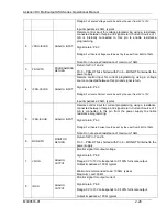
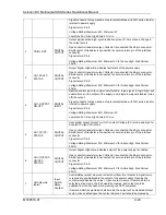
Open collector transistor output, Collector is connected the 26-pin connector.
Emitter point of transistor is connected to common return pin of the interface
connector.
Signal return: Pin 26
Voltage Rating: Maximum 30V, Minimum 3V for Active High, Sink Current:
50mA
24
CH3-OUTPUT-
ON/OFF-
STATUS
DIGITAL
OUTPUT
Output Signal, High state indicates output of the power supply is enabled.
Open collector transistor output, Collector is connected the 26-pin connector.
Emitter point of transistor is connected to common return pin of the interface
connector.
Signal return: Pin 26
Voltage Rating: Maximum 30V, Minimum 3V for Active High, Sink Current:
50mA.
25
CH3-Remote
Inhibit
Input
Switch/
Relay
Contact
Switch/Relay contact closure or direct short from this terminal to signal return
is required to enable/disable the output of the power supply. Opening the
contact would disable the output. Upon contact closure, if remote inhibit is
selected as live mode, the fault would be cleared, and output could be
enabled from the front panel or by issuing the SCPI command.
If remote inhibit is selected as Latch mode, the output will be disabled, Output
could not be enabled upon the contact closure. Fault should be cleared by
issuing the SCPI command OUTP<n>:PROT:CLE or by clearing the fault from
the front panel screen.
Remote circuit must sink up to 10 mA from 5 VDC to enable.
Signal return: Pin 26
26
RTN
RETURN
Return/GND. Pins 8,17 and 26 are shorted internal to the power supply.
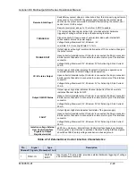
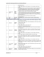
Table 2-15: External User Control Interface Pin Out details
CAUTION!
All the three channels signal returns (Pin 8, 17 and 26) are shorted internally to the
power supply. Applying a voltage potential between them would damage the power
supply.
CAUTION!
External User Control interface signals are isolated from negative output terminal;
Isolation voltage is rated for ±600 V
RMS
, maximum; operation of Isolated Analog
Interface signals should be at SELV safety voltage conditions to chassis ground.
2.12.3
RS-232C Serial Interface
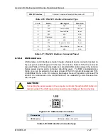
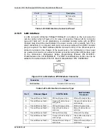
RS-232C Figure 2-12, Table for connector type and Table 2-17 for pin descriptions.
The power source functions as Data Circuit-terminating Equipment (DCE). The cable
connecting to the Data Terminal Equipment (DTE) should be straight-through (one-to-
one contact connections). For EMC considerations a ferrite core can be added to the
cable Ametek P/N: 991-642-28, Manufacturer P/N: CS28B0642. Refer to the DC-
Asterion Multioutput Series Programming Manual P/N M330517-01 distributed on the
CD, M550008-01 for establishing communication from the computer.
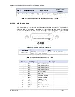
Figure 2-12: RS-232C Interface Connector
Connector
Type

