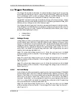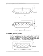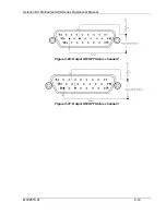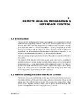
M330516-01
4-1
4
REMOTE EXTERNAL USER INTERFACE
CONTROL
4.1
Introduction
The Power supply provided with External User Interface Control connector on the rear
panel allows the unit to be configured for different operating configurations of each
channel. This chapter contains setup and operating configuration of Output ON/OFF,
Regulation Mode status, Fault status, Remote inhibit (E-stop) and Trigger Functions.
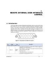
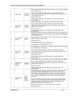
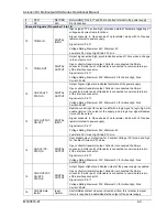
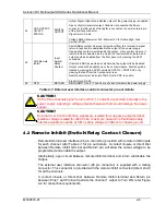
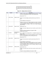
Refer to Figure 4-1 for the connector pin-out diagram and Table for connector pin-out
details. The setup and operating requirements of each configuration are provided in
Sections 4.2 and 4.3.
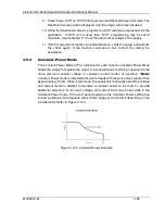
Figure 4-1: External User Interface Connector
Pin
Signal
Type
Description
Channel-1 Signals (Pin number 1 to 9)
1
TRIG1-IN
DIGITAL
INPUT
Input signal, TTL active-high; provides external hardware triggering of
voltage and current ramp functions.
Signal connects to Open-anode of opto-
isolator diode with 1kΩ series
resistor internal to power supply.
Signal return: Pin 8
Voltage Rating: Maximum 24V, Minimum -5V
Low state 0.3V max, High State 2.7V min.

