Asterion DC Multioutput ASA Series Operational Manual
M330516-01
5-8
•
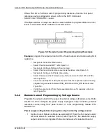
Connect an DC voltage source across the respective channel analog
programming connector between IPRG_VSOUR and PRG_RTN terminal and
apply 8.5V (85% of FSC); refer .
•
Verify the output current from the measurement screen for respective channel;
refer Figure 5-5.
5.4
Remote Voltage Programming
Remote voltage programming is summed with Full Scale value on the front panel or
digital setting for individual channels. Remote voltage programming configuration is
used for applications that require the output voltage be programmed (controlled) from
a remote instrument. An external resistance or external voltage source can be used
as a programming device. When using remote voltage programming, a shielded,
twisted-pair cable is recommended to prevent noise interference to programming
signals.
Remote Voltage Programming configurations given below is with reference to channel
1. The same configuration is to be followed for the other two channels (channel 2 and
channel 3). i.e. wherever channel 1 is stated it should be replaced and followed for the
selected channel (channel 2 or channel 3).
5.4.1
Remote Voltage Programming by Resistance
Programs the output voltage of the supply by external resistive reference source. Refer
Section 3.4.9.3 to configure the power supply to program output voltage by external
reference source using front panel screen or refer programming manual P\N:
M330517-01.
Power supply configurations to program output voltage by resistance:
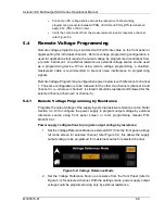
1. Set the Voltage Reference Mode as external (EXT) from the front panel voltage
ref mode screen for selected channel; refer Figure 5-8, this allows the supply
output voltage to be programed form external source for selected channel.
Figure 5-8: Voltage Reference Mode
2. Set the Voltage Reference Source as resistive from the front Panel (refer to
Figure 5-3) for selected channel. With the settings made, power supply output
voltage could be programed using only by external resistance.

