Asterion DC Multioutput ASA Series Operational Manual
M330516-01
2-28
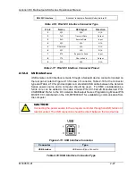
Pin #
Name
Description
1
N/C
No Connection
2
D-
Data -
3
D+
Data +
4
GND
Ground
Table 2-19: USB Interface Connector Pinout
2.12.5
LAN interface
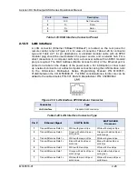
A LAN connector (Ethernet 10BaseT/100BaseT) is located on the rear panel for
remote control; refer to Figure 2-14 for view of connector, Table 2-20 for connector
type and Table 2-21 for pin descriptions. A standard modular cable with an 8P8C
modular plug should be used between the power source and a network hub. For a
direct connection to a computer LAN card, a crossover cable with an 8P8C modular
plug is required. The MAC Address (Media Access Control) of the Ethernet port is
printed on a label on the chassis of the power source. For information on how to set
up a network connection or a direct computer connection using the LAN interface, refer
to the DC-Asterion Multioutput Series Programming Manual P/N M330517-
01distributed on the CD, M550008-01. For EMC considerations a ferrite core can be
added to the cable Ametek P/N: 991-642-28, Manufacturer P/N: CS28B0642.
Figure 2-14: LAN Interface 8P8C Modular Connector
Connector
Type
LAN Interface
Standard RJ45 connector
Table 2-20: LAN Interface Connector Type
Pin #
Ethernet Signal
EIA/TIA 568A
EIA/TIA 568B
Crossover
1
Transmit/Receive Data 0 +
White with green stripe
White with orange stripe
2
Transmit/Receive Data 0 -
Green with white stripe or
solid green
Orange with white stripe or
solid orange
3
Transmit/Receive Data 1 +
White with orange stripe
White with green stripe
4
Transmit/Receive Data 2 +
Blue with white stripe or
solid blue
Blue with white stripe or
solid blue
5
Transmit/Receive Data 2 -
White with blue stripe
White with blue stripe
6
Transmit/Receive Data 1 -
Orange with white stripe or
solid orange
Green with white stripe or
solid green
7
Transmit/Receive Data 3 +
White with brown stripe or
solid brown
White with brown stripe or
solid brown


