


Asterion DC Multioutput ASA Series Operational Manual
M330516-01
4-9
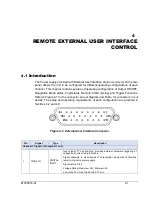
4.4
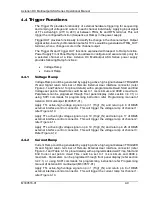
Trigger Functions
The Trigger IN provides functionality of external hardware triggering for sequencing
and ramping of voltage and current in each channel individually. Applying input signal
of TTL active-high (2.7V to 24V) at between TRIG_IN and RTN terminal. This will
trigger the configured function (Sequence or Ramp) in the power supply.
Trigger OUT provides functionality to identify the change in the channel output. Output
signal active-low of synchronization pulse for 10 ms would be generated at TRIG_OUT
terminal, when a change occurs in the channel output.
The Trigger IN and Trigger OUT functions explained with respect to Ramp function.
Power Supply Front Panel Ramp menu allows to configure and execute ramp only for
a selected channel at a time. Asterion DC Multioutput ASA Series power supply
provides following Ramp functions:
•
Voltage Ramp
•
Current Ramp
4.4.1
Voltage Ramp
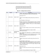
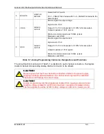
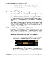
Voltage Ramp could be generated by applying active high signal between TRIGGER
IN and Signal return terminal of Remote External User interface connector (refer
Figure 4-1 and Table 4-1 for pinout details) with a programmable Dwell, Start and End
Voltage set points. Dwell time could be set to 1 ms minimum and 9999 s maximum.
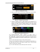
Parameters can be programed through front panel display (refer section 3.4.7.1) or
using SCPI commands for programming instruction refer Programming manual of
Asterion DC multioutput (M330517-01).
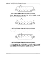
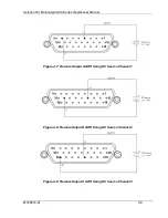
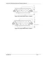
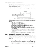
Apply TTL active-high voltage signal on pin 1 (Trig1_IN) and return pin 8 of DB26
external interface control connector. This will trigger the voltage ramp of channel 1;
refer Figure 4-10.
Apply TTL active-high voltage signal on pin 10 (Trig2_IN) and return pin 17 of DB26
external interface control connector. This will trigger the voltage ramp of channel 2;
refer Figure 4-11.
Apply TTL active-high voltage signal on pin 19 (Trig3_IN) and return pin 26 of DB26
external interface control connector. This will trigger the voltage ramp of channel 3;
Refer Figure 4-12.
4.4.2
Current Ramp
Current Ramp could be generated by applying active high signal between TRIGGER
IN and Signal return terminal of Remote External User interface connector (refer
Figure 4-1 and Table 4-1 for pinout details) with a programmable dwell Time, Start and
End Current set points. dwell Time could be set to 1 ms minimum and 9999 s
maximum. Parameters can be programed through front panel display (refer section
3.4.7.1) or using SCPI commands for programming instruction refer Programming
manual of Asterion DC multioutput (M330517-01).
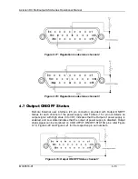
Apply TTL active-high voltage signal on pin 1 (Trig1_IN) and return pin 8 of DB26
external interface control connector. This will trigger the current ramp for channel 1;
refer Figure 4-10.