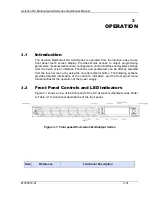
Asterion DC Multioutput ASA Series Operational Manual
M330516-01
3-33
signals for all the 3 channels connected (Pin-7 shorted to Pin-8 to enable channel-1, Pin-
16 shorted to Pin-17 to enable channel-2, Pin-25 shorted to Pin-26 to enable channel-3)
to allow the output to be enabled.
WARNING!
The power-up factory default state is output enabled, and the output will be
energized with the settings of voltage and current at zero. At initial power-
on a screen is displayed with a warning that the output will be enabled after
countdown of a 10-second timer; during this state, the output Voltage and
Current are programmed to zero, the Overvoltage Protection (OVP) is set
to maximum, and the Output State is OFF. After the 10-second timer has
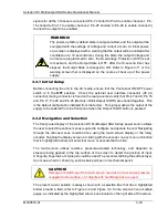
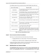
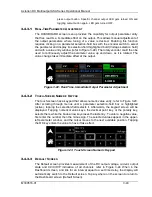
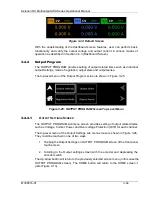
elapsed, the Output State is changed to ON. Refer to Figure 3-11 or the
warning screen that is displayed on the course of boot up of the power
supply.
3.3.1
Initial Setup
Before connecting the unit to the AC mains, ensure that the front panel ON/OFF power
switch is in the
OFF
position. Check the external user interface connector (26 pin
connector) mating connector is fixed on the rear panel and verify that Pins 7 and 8, Pin 16
and Pin 17, Pin 25 and Pin 26 (Remote Inhibit Output On/Off) are shorted together. This
is the default configuration installed from the factory. This jumper allows the output of the
supply to be enabled from the front panel when the Output On/Off button is pressed.
3.3.2
Navigation and Selection
The front panel display of the Asterion DC Multioutput ASA Series power source allows
the user to select the various menus required to configure and operate the unit. Navigating
through the various menus could be done using the touch-screen display or the rotary
encoder. Tapping the display screen or clicking with the encoder on any menu or function
that is highlighted (active) will enter that menu or execute that function.
The touch-screen utilizes resistive, pressure-actuated technology, and depends on
pressure being applied to the top surface of the screen to detect the position of input.
A fingertip, fingernail, or stylus pen could be used. To prevent scratching the surface layer,
do not use a hard or sharp tip, such as ball-point pen or mechanical pencil.
CAUTION!
Damage or scratching of the touch-screen could occur if excessive pressure
is applied to the surface, or if objects with hard/sharp tips are used.
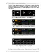
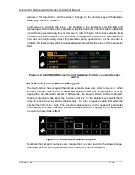
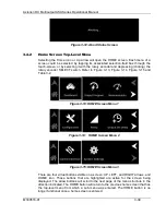
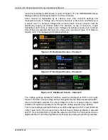
The present cursor position is always shown with a selection-box that has a highlighted
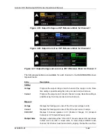
border around a field, refer to Figure 3-2 and Figure 3-3. Some screens have multiple
pages, as indicated by the highlighted Arrow icons located on the right side of the screen.


