Ala
rm L
ist
Ala
rm
Numb
er
(
0
00
0 to
09
99)
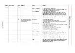
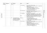
Alarm List-112
60
An error occurred during the
parameter/file transfer to the
1st functional safety board.
Setting error
(1)Check the following settings.
∙
Control group settings in maintenance mode
∙
The YSF25 board (#1) rotary switch setting (0).
∙
The EAXA21 board rotary switch setting (0) of the corresponding
node number (SV#1)
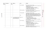
Connection failure
(1)Turn the power OFF then back ON.
(2)If the alarm occurs again, check the connection and insertion of the
following connector.
∙
CN509 cable of EAXA21 board
∙
The cable of EAXA21 board connector CN515/516
∙
CNBXconnector of EAXA21board and YSF25 board
∙
The PCI connector of YIF01board
∙
The cable of YIF01 board connector CN113
YSF25 board failure
(1)Turn the power OFF then back ON.
(2)If the alarm occurs again, replace the YSF25 board. Save the
CMOS.BIN before replace the board to be safe.
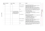
YIF01 board failure
(1)Turn the power OFF then back ON.
(2)If the alarm occurs again, replace the YIF01 board. Save the
CMOS.BIN before replace the board to be safe. Replace the YIF01
board, and then load the CMOS.BIN saved before alarm occurred.
other
If the alarm occurs again, save the CMOS.BIN in maintenance mode,
and then contact your Yaskawa representative about occurrence
status (operating procedure).
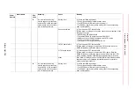
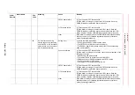
61
An error occurred during the
parameter/file transfer to the
2nd functional safety board.
Setting error
(1)Check the following settings.
∙
Control group settings in maintenance mode
∙
The YSF25 board (#2) rotary switch setting (1).
∙
The EAXA21 board rotary switch setting (1) of the corresponding
node number (SV#2)
Alarm
Number
Alarm Name
Sub
Code
Meaning
Cause
Remedy


