


Ala
rm L
ist
Ala
rm
Numb
er
(
0
00
0 to
09
99)
Alarm List-48
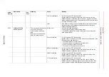
15
An error was detected in
communications with the I/O
module board connected with
15th serial bus when the
control power turned ON.
Setting error
(1)Check the following settings.
∙
The rotary switch setting which specifies slot numbers of each I/O
module
∙
I/O module settings in maintenance mode
Please refer to the manual of each IO module for the details of the
setting.
Connection failure
(1)Turn the power OFF then back ON.
(2)If the alarm occurs again, check the connection and insertion of the
following cables and connectors.
∙
The M
ǁ
communications cable which I/O module of the corresponding
node number
∙
(In case of M
ǁ
communications last station) Terminator
∙
24V power of the corresponding I/O module
I/O module failure
(1)Turn the power OFF then back ON.
(2)If the alarm occurs again, replace the following board. Save the
CMOS.BIN before replace the board to be safe.
YIF01 board failure
(1)Turn the power OFF then back ON.
(2)If the alarm occurs again, replace the YIF01 board. Save the
CMOS.BIN before replace the board to be safe. Replace the YIF01
board, and then load the CMOS.BIN saved before alarm occurred.
other
If the alarm occurs again, save the CMOS.BIN in maintenance mode,
and then contact your Yaskawa representative about occurrence
status (operating procedure).
16
An error was detected in
communications with the I/O
module board connected with
1st PCI connector when the
control power turned ON.
Setting error
(1)Check the following settings.
∙
PCI slot number in which each PCI board is mounted
∙
I/O module settings in maintenance mode
Please refer to the manual of each IO module for the details of the
setting.
Connection failure
(1)Turn the power OFF then back ON.
(2)If the alarm occurs again, check the connection and insertion of the
following connector.
∙
The PCI connector of the corresponding I/O module
Alarm
Number
Alarm Name
Sub
Code
Meaning
Cause
Remedy


