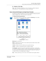
Machinery Balancing Module
How to Set Up the Microlog for a Single
-Plane Procedure
The
Variable
sensor option allows you to configure settings for a
sensor that is not on the sensor list.
Typically, accelerometers are used to perform velocity
measurements for field balancing procedures.
A
Manual Entry
option is available at the end of the list for
manual balancing data entry, allowing you to review and change
balancing run data. If selected, you are prompted to manually
enter the running speed, vibration magnitude, and phase angle
for the balancing runs.
Sensor Units –
(Not editable if a preconfigured sensor is selected in the
Sensor
field.)
When the
Variable
sensor is selected, select the measurement units to use for the type
of sensor being used. Options in
clude
g
,
in/s
, or
mil
.
Sensitivity –
(Not editable if a preconfigured sensor is selected in the
Sensor
field.)
When the
Variable
sensor is selected, use the alphanumeric keypad to enter transducer
sensitivity in millivolts (mV) per Engineering Unit (EU).
Input Range
– (Available only if the system
Setup
menu’s
Input Range
setting is set to
Sensor Units
.) Select the signal input range as a fixed range in transducer units in a 1
- 2 - 5 sequence. (The available fixed values vary depending on the transducer type
being used.)
If a fixed range is selected and the Microlog detects an over range,
it automatically selects the next higher range until it does not over
range.
ICP Power –
(
On
or
Off
),
(Not editable if a preconfigured sensor is selected in the
Sensor
field.) When the
Variable
sensor is selected, select to turn ICP power
Off
or
On
for the sensor.
Display Units
– Specify the unit of measurement for the select sensor type. The
options available in the list vary depending on the sensor selected.
Detection
– Determines signal detection and scaling. Detection options include
Peak
,
Pk-Pk
, and
RMS
. The default setting is
Peak
for acceleration and velocity, and Peak-
to-Peak (
Pk-Pk
) for displacement.
Weight Units
– Select the units of measurement used for your trial, correction, and
trim weights.
Options include:
g
,
kg
,
cm
,
mm
,
oz
,
lb
,
in
,
EU
or
%
.
Length Units
– Select the units of measurement used for measuring the radius of the
weight placement (from the shaft center to the position of the weight). Either
inch
,
feet
,
EU
. This information is used if you wish the Microlog to estimate your trial weight
for you.
Trigger – Manual
or
Visual
. (Available only if the
Setup
screen’s
Trigger
field is set to
User
.) Determines how the trigger level is entered when setting up measurements that
require a trigger, either manually as numeric input in the subsequent
Trigger Level
field, or visually using a graphic representation of the trigger signal and trigger level.
Manual
–
When set to
Manual
, you will enter the trigger level in volts as
numeric input in the
Trigger Level
setup field.
5 - 6
SKF Microlog - GX Series
User Manual


