


5
Machinery Balancing Module
Microlog Balancing Overview
The easy to use Microlog Balancing application resolves single-plane, two-plane, and
static-couple balances with high precision. Clear, comprehensive setup menus and
easy-to-follow display screens with graphical data representations make for easy
operation.
Warning - Due to required accessories, this module is not for use in Class I
Division 2 hazardous locations. Restrictions apply when used in ATEX zone 2
hazardous locations. Reference this manual's Appendix D, Safety Instructions for
details.
The Microlog is designed to interface with off-the-shelf laser tachometers, optical
tachometers, or stroboscopes for balancing phase measurements.
For focus and ease of use, this chapter overviews and details Microlog procedures for
single-plane, two-plane, and static-couple balancing in separate sections.
Measurement Trigger Requirements
Machine balancing requires a 1 X trigger signal. The trigger signal is normally obtained
from the ± TTL
output of one of four triggers:
•
Buffered outputs
•
Laser tachometer
•
Reflective systems
•
SKF StrobeLite
Single-Plane Balancing Overview
Regardless of whether you are performing a single or two-plane balancing procedure,
all balancing procedures progress through basic “runs” as you start (spin) and stop the
rotor.
For two-plane procedures, you perform some of the runs twice,
once with weights on correction plane one and again with weights
on correction plane two. For simplicity, the following example
describes a single-plane procedure.
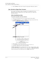
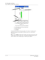
1 - Set Up Balancing Equipment and Measurement Parameters
Stop
- First, with the machine stopped, set up the balancing equipment and mark your
tachometer reference point on the rotor or shaft. Use Microlog Setup menu options to
configure balancing measurement parameters for the balancing run sequence.
SKF Microlog - GX Series
5 - 1
User Manual


