


Idler Sound Monitor Module
Hardware Setup
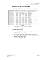
Figure 11 - 7.
Microlog with Adapter Plate Assembly Attached.
To attach the adapter plate assembly:
•
Lay the Microlog face down.
•
Position the adapter plate over the Microlog’s battery compartment so the adapter
plate’s two bottom pins align with the holes adjacent to the battery cover screws -
and the locking screw’s hole aligns with the recessed screw mount at the top of the
battery cover.
•
Gently press the two bottom pins into the holes adjacent to the battery cover
screws until the pins snap into place.
•
Fasten the locking screw into the recessed screw mount at the top of the battery
cover to secure the adapter plate.
•
Place the Microlog’s rubber boot over the Microlog (over the adapter plate) to firmly
secure the adapter plate and to provide a more secure fit when attaching the
microphone / parabolic reflector to the adapter plate (below).
To attach the microphone / parabolic reflector to the adapter plate:
It is easiest to first attach the head phone adapter cable to the
Microlog, then connect the parabolic reflector to the back of the
Microlog.
In the center of the attached adapter plate, there are two mounting studs for
connecting to the parabolic reflector handle. On the parabolic reflector handle, there
are two slots for connecting to these mounting studs.
•
Position the parabolic reflector handle’s mounting slots over the adapter plate’s
mounting studs and slide the parabolic reflector handle toward the top of the device
to secure the parabolic reflector handle to the adapter plate.
•
Secure loose cable using the Velcro strap on the right-side of the adapter plate and
then connect the cable’s connector to the Microlog’s
CH1
connector at the top of
the device.
11 - 8
SKF Microlog - GX Series
User Manual


