


Frequency Response Function Module
Recording the Measurement
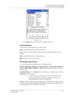
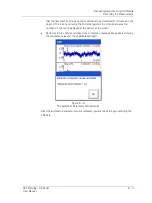
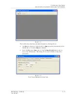
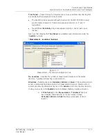
Figure 8 - 7.
Example of
Taking Data
Mode.
The data is collected in the same way as when setting up the automatic parameters, by
hitting the hammer against the object on the side opposite to the accelerometer. The
text box at the bottom of the screen indicates how many hits you need to take, based on
the
Num of Averages
setting in
FRF – Setup
.
The Microlog’s LED indicators provide feedback on the hammer hits:
•
The Microlog’s red LED indicates an error (e.g., input overrange) during data
acquisition.
•
The am
ber LED indicates the Microlog is initializing the measurement.
•
The green LED indicates the Microlog is collecting data (in Hammer mode, it is
looking for a hit).
If the
Accept
/
Reject
option in
FRF - Setup
was set to
Automatic
, each time a hammer
hit is collected the Microlog automatically determines if the data is correct. If it is not, a
message appears with details on why the hit was rejected.
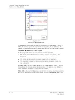
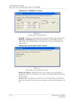
If
Accept
/
Reject
was set to
Manual
, you see the hammer and response time waveforms
for both the hammer and accelerometer outputs, and then an
Accept / Reject
prompt.
8 - 10
SKF Microlog - GX Series
User Manual


