


7 Detailed function description SV800/SV800A User Manual
144
nameplate parameters are used during running and self-learning of the motor parameters, so
they must be set before self-tuning. When the motor terminal has multiple wiring combinations,
be sure to determine the motor rating under the current wiring mode. When setting the rated
motor speed, it is combined with E0-00 (rotation speed / frequency upper limit).
In vector control mode (IM.SVC, IM.VC), the motor cooling mode needs to be set correctly.
During vector control, the change of the motor parameters is compensated according to the
temperature change of the motor (different from the compensation performed by detecting the
temperature of the motor). B1-06 (forced cooling fan or water cooling) is set to 1 when the
motor cooling fan is driven by another motor or the motor is water-cooled; when the fan directly
connected to the motor shaft is cooled by the rotation of the motor itself, b1-06 (self-cooling fan)
is set to 0.
The input range of this group of parameters is limited. The power range of the motor that can be
driven by a certain power inverter is limited. Therefore, if the setting exceeds the limit when
setting the nameplate, SEtE (parameter setting error) fault will be displayed. This fault cannot
be reset. It disappears automatically when the setting is correct.
When the control mode is V/F control (IM.VF), the motor nameplate parameters are initialized
to the nameplate of the same type of power motor, which may not match the nameplate of the
motor being driven. The motor nameplate parameters are initialized to during vector control,
regardless of vector or V/F control mode, please perform motor self-learning as much as
possible.
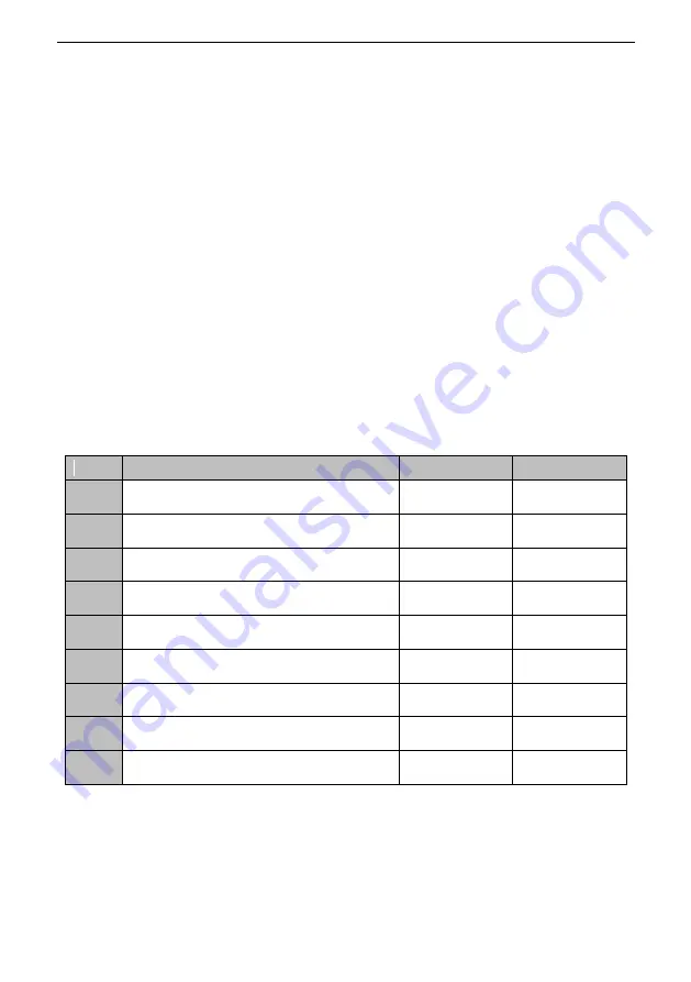
No.
Name
Set range
Factory default
b1-08
First motor primary side resistance
Determined with the
model
Change with the model
(m Ω)
b1-09
First motor secondary side resistance
Determined with the
model
Change with the model
(m Ω)
b1-10
First motor leakage inductance
Determined with the
model
Change with the model
(m H)
b1-11
First motor mutual inductance
Determined with the
model
Change with the model
(m H)
b1-12
First motor inductance saturation compensation
coefficient 1
Determined with the
model
Change with the model
(0.0%)
b1-13
First motor inductance saturation compensation
coefficient 2
Determined with the
model
Change with the model
(0.0%)
b1-14
First motor iron loss conductance
0.0mho
~
600.0mho
Change with the model
(0.0mho)
b1-15
First motor loss factor 1
0.0%
~
200.0%
Change with the model
(0.0%)
b1-16
First motor loss factor 2
0.0%
~
200.0%
Change with the model
(0.0%)
The set of parameters is the motor electrical constant necessary for vector control operations.
When b0-02 (DC mode self-learning) is set to 1, b1-08 (first motor primary side resistance) is
automatically set; When b0-02 (full-mode self-learning) is set to 2, all parameters are
automatically set. Motor electrical constants are usually obtained by self-learning of motor
parameters. If full-mode self-learning cannot be performed, manually enter this group of
parameters and perform DC mode self-learning. If manually set according to the motor design


