118
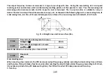
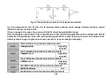
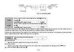
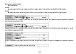
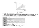
Fig. F2-1 Steady State Equivalent Circuit of Asynchronous Motor
Fig. F2-1 parameters R1, X11, R2, X21, Xm, I0 represent stator resistance, stator leakage inductive reactance, mutual
inductive resistance, no-load current.
If there is tuning for the motor, the set value of F2.06~F2.10 will be updated after tuning.
After modifying the rated power F2.01 of asynchronous motor, F2.03~F2.10 parameters will be updated with default
parameters of asynchronous motor with corresponding power (F2.02 is rated frequency of motor, not included in the
default parameter range of asynchronous motor, and need to be set according to nameplate).
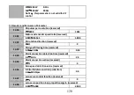
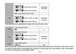
F2.11
Stator resistance of synchronous motor (reserved)
0.001
~
20.000Ω
Depending
on model
F2.12
D-axis inductance of synchronous motor (reserved)
0.1
~
6553.5mH
Depending
on model
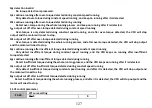
F2.13
Q-axis inductance of synchronous motor (reserved)
0.1
~
6553.5mH
Depending
on model
F2.14
Back-EMF constant of synchronous motor (reserved)
1
~
1000V/1000rpm
150
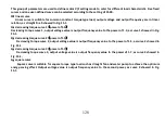
F2.15
Identification current of synchronous motor (reserved)


