Appendix
R&S
®
Spectrum Rider FPH
466
User Manual 1321.1011.02 ─ 06.00
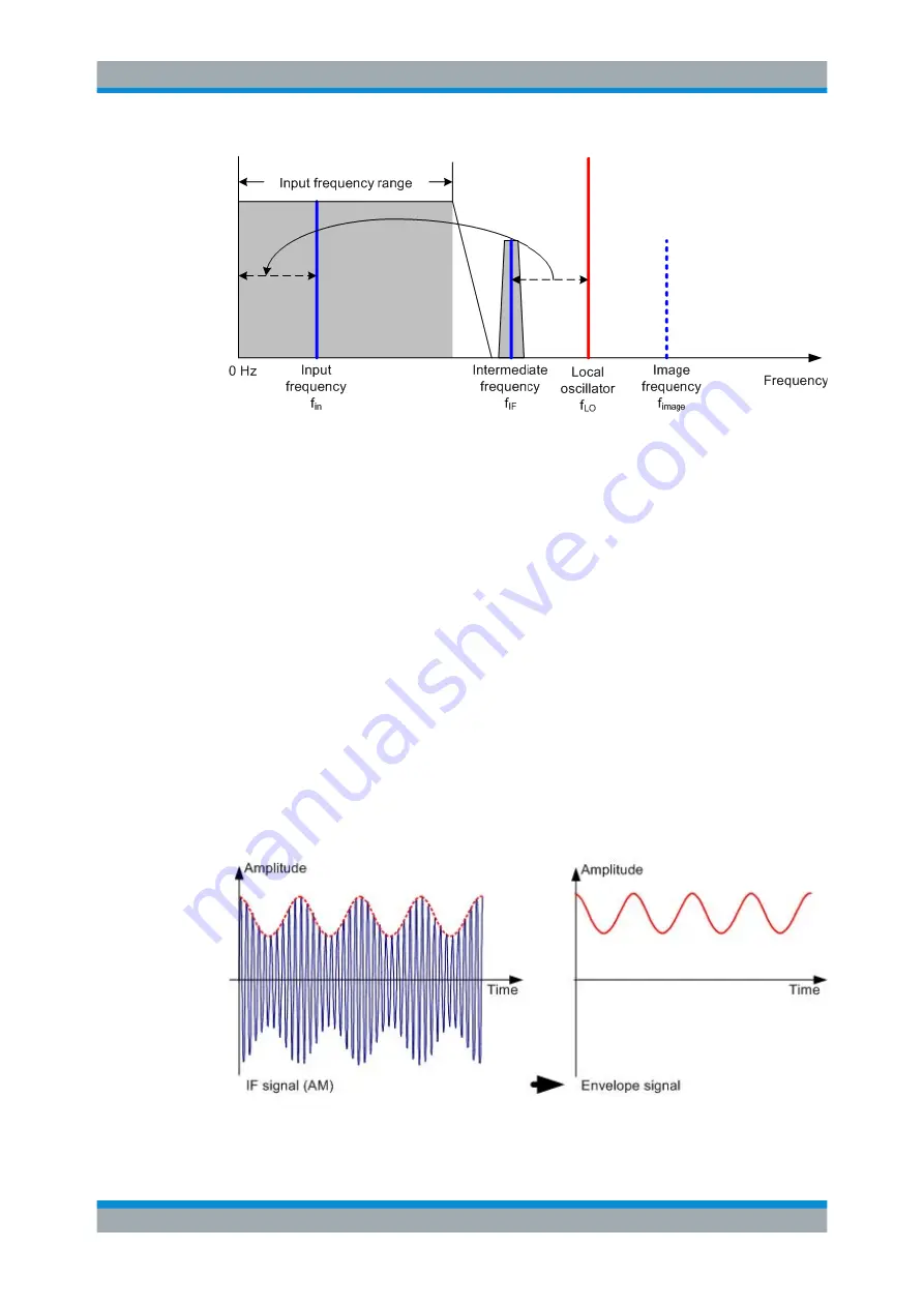
The first local oscillator is tuned with a sawtooth which simultaneously acts as the x
deflection voltage for the display. In practice, synthesizer technology is used to gener-
ate the frequency of the first local oscillator and for a digital display.
The instantaneous sawtooth voltage therefore determines the input frequency of the
spectrum analyzer.
The bandwidth of the IF filter at the IF determines the bandwidth that is used for mea-
surements. Pure sine signals are passed by the IF filter characteristics. This means
that signals closer together than the bandwidth of the IF filter cannot be resolved. This
is why the bandwidth of the IF filter in a spectrum analyzer is referred to as the resolu-
tion bandwidth. The R&S Spectrum Rider has resolution bandwidths from 1 Hz to 3
MHz.
The bandlimited IF is passed to the envelope detector. The envelope detector removes
the IF from the signal and outputs its envelope. The output signal from the envelope
detector is referred to as the video signal. As it has been demodulated, it only contains
amplitude information. The phase information is lost.
With RF sine signals, the video signal is a DC voltage. With AM signals the video sig-
nal contains a DC component whose amplitude corresponds to the carrier power and
an AC component whose frequency is equal to the modulation frequency, provided the
modulation frequency is inside the resolution bandwidth.
The video filter comes after the envelope detector. The filter is a lowpass with an
adjustable cutoff frequency which limits the bandwidth of the video signal. It is particu-
How a Spectrum Analyzer Works


