Spectrum Analyzer Mode
R&S
®
Spectrum Rider FPH
137
User Manual 1321.1011.02 ─ 06.00
2. Select the "Meas Mode" softkey.
3. The R&S Spectrum Rider opens a submenu to select the measurement mode.
4. Select the "Spectrum Emission Mask"" menu item.
The R&S Spectrum Rider starts to measure the spectrum emission mask.
Note that the frequency range of the actual measurement depends on the start and
stop frequency you have set on the R&S Spectrum Rider. Correct measurement results
are therefore only possible if the frequency ranges of the SEM are inside the current
span of the R&S Spectrum Rider.
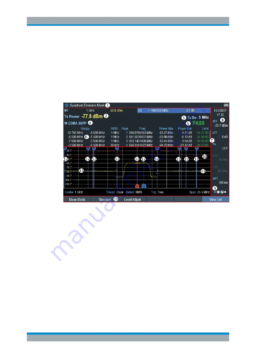
Figure 6-5: Screen layout for the SEM measurement
1 = SEM measurement mode
2 = Tx power measurement
3 = Tx bandwidth
4 = Measurement standard
5 = Limit check result
6 = SEM measurement list
7 = Scroll bar for SEM measurement list
8 =
Parameter view
9 =
10 = Spectrum emission mask (red line)
11 = Trace (yellow line)
12 = Peak (P<x>) and normal marker (M<x> and D<y>)
13 = SEM softkey menu
Markers in the SEM measurement
In addition to the normal marker functionality of the R&S Spectrum Rider, the SEM
measurement provides special markers labeled P1 to Px.
The R&S Spectrum Rider activates and positions these special markers automatically
after displaying the trace. Each of these markers marks the peak level in each SEM
Performing Spectrum Measurements


