T
echnical
B
ulletin
PAGE: 6/11
Reissued:04-Jul-12
Model:
Taurus-C1/P1 (D074/D075/M044)
Date:
24-Oct-11
No.:
RD074029d
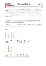
Appendices – Location of the Shock Jitter for each Paper Size
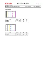
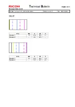
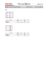
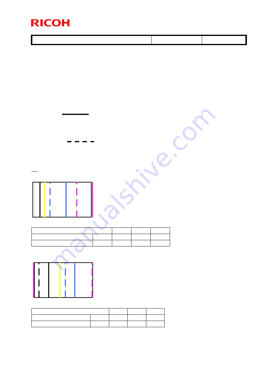
The following illustrations and tables show where the shock jitter appears on each
standard size paper in simplex printing. The values in the table are distances (millimeters)
from the leading edge of the paper. Note that the location of the shock jitter will vary if you
change the CPM.
A solid line (
) indicates the location of the shock jitter as a result of Cause 1;
shock generated when the leading edge enters the nip between the ITB and PTR.
Lines are color coded to indicate the station.
A dotted line (
) indicates the location of the shock jitter as a result of Cause
2; shock generated when the trailing edge exits the nip between the ITB and the PTR.
Lines are color coded to indicate the station.
A3
C1a BK
C
M
Y
Cause 1
51 241 - 85
Cause 2
- 125
315 -
C1b Bk
C
M
Y
Cause 1
101 291 - 184
Cause 2
34 224 414 118


