T
echnical
B
ulletin
PAGE: 2/16
Model:
Taurus-C1/P1 (D074/D075/M044)
Date:
10-Apr-12
No.:
RD074060
1. Skew Correction
1-1. Perpendicularity adjustment
1-2. Achieving the recommended skew range
1-3. Possible problems involving skew correction
1-1. Perpendicularity adjustment
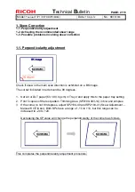
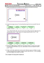
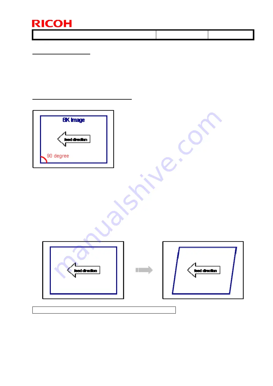
Check if skew in the main scan direction is exhibited on a BK image.
The corner indicated in red should be 90 degrees.
1. Set A3 or DLT paper (63.1-80.0 gsm) in Tray 2 and apply this to the paper tray setting.
2. Print 5 copies of the test pattern Trimming Area (SP2109-003-14) in b/w and simplex.
3. If the corner is not 90 degrees, adjust SP2104-40 and SP2104-41 (Skew Adjustment –
Manual K CE/User). Both SPs have a range of -10 to +10, but this range can be
increased to -20 to +20.
Decreasing the SP value will change the perpendicularity of the corners as follows.
This completes the perpendicularity adjustment procedure.

