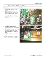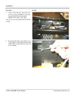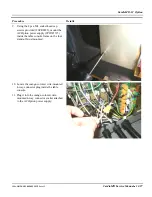
CardioMD AC Option
1MAN0158-H11 04-2005 CSIP Level 1
CardioMD Service Manual
12-93
Procedure Details
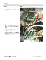
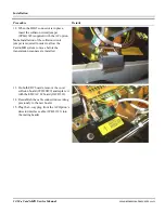
9.
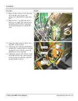
Remove the CANbus terminator from
connector A3 on the EDC board on
detector 1.
10.
Connect the AC Option’s CANbus
interface cable (9CBL1314) to connector
A3 on the EDC board of detector 1.
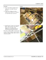
11.
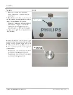
On each detector, mount one of the female
DB15 connectors that are part of the AC
Option’s detector interface cable
(9CBL1313) on the brackets provided.
Use the threaded stand-offs provided.
Note
. The two female DB15 connectors that
are part of the AC Option’s detector interface
cable carry identical signals. Hence, they are
not detector-specific.
Threaded stand-off
Содержание CARDIOMD
Страница 1: ...CARDIOMD SERVICE MANUAL 1MAN0158 H11 04 2005 CSIP Level 1 ...
Страница 10: ...Introduction x CardioMD Service Manual 1MAN0158 H11 04 2005 CSIP Level 1 ...
Страница 16: ...Safe Operating Practices 1 6 CardioMD Service Manual 1MAN0158 H11 04 2005 CSIP Level 1 ...
Страница 164: ...Detector Calibration Files 5 60 CardioMD Service Manual 1MAN0158 H11 04 2005 CSIP Level 1 ...
Страница 207: ...Installation 1MAN0158 H11 04 2005 CSIP Level 1 CardioMD Service Manual 8 5 Figure 8 2 System footprint with short table ...
Страница 232: ...Installation 8 30 CardioMD Service Manual 1MAN0158 H11 04 2005 CSIP Level 1 Figure 8 17 Installation template ...
Страница 328: ...Installation Procedures 9 38 CardioMD Service Manual 1MAN0158 H11 04 2005 CSIP Level 1 ...
Страница 348: ...Planned Maintenance Procedures 11 6 CardioMD Service Manual 1MAN0158 H11 04 2005 CSIP Level 1 ...
Страница 465: ......


