False Collisions
5-20
CardioMD Service Manual
1MAN0158-H11 04-2005 CSIP Level 1
5.5.1.1
Disabling Detector Edge Sensors and Detector End Cover Sensors
Detector edge sensors and detector end cover sensors should be disabled on both detectors.
Proceed as follows:
Procedure Details
1.
Remove the detector side cover
2.
Remove the detector edge cover.
3.
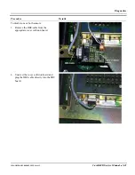
Locate the connectors for the end cover
sensor and for the edge sensor. See photo
on the right.
4.
Disconnect one or both of the sensors as
required.
5.
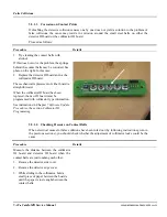
Place two jumpers on each connector as
shown in photo.
This will establish a 20 k
Ω
substitute
resistance for each of the disconnected
sensors.
5.5.1.2
Disabling Detector Top Cover Sensor and Rotate Gear Cover Sensor
Procedure Details
1.
Remove the detector top cover.
2.
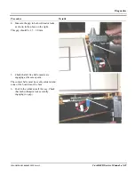
Locate the two cover collision boards.
The collision board that plugs into the EDC
board of detector 1 serves the detector top
cover sensor.
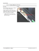
The collision board that plugs into the EDC
board of detector 2 serves the rotate gear cover
sensor.
Содержание CARDIOMD
Страница 1: ...CARDIOMD SERVICE MANUAL 1MAN0158 H11 04 2005 CSIP Level 1 ...
Страница 10: ...Introduction x CardioMD Service Manual 1MAN0158 H11 04 2005 CSIP Level 1 ...
Страница 16: ...Safe Operating Practices 1 6 CardioMD Service Manual 1MAN0158 H11 04 2005 CSIP Level 1 ...
Страница 164: ...Detector Calibration Files 5 60 CardioMD Service Manual 1MAN0158 H11 04 2005 CSIP Level 1 ...
Страница 207: ...Installation 1MAN0158 H11 04 2005 CSIP Level 1 CardioMD Service Manual 8 5 Figure 8 2 System footprint with short table ...
Страница 232: ...Installation 8 30 CardioMD Service Manual 1MAN0158 H11 04 2005 CSIP Level 1 Figure 8 17 Installation template ...
Страница 328: ...Installation Procedures 9 38 CardioMD Service Manual 1MAN0158 H11 04 2005 CSIP Level 1 ...
Страница 348: ...Planned Maintenance Procedures 11 6 CardioMD Service Manual 1MAN0158 H11 04 2005 CSIP Level 1 ...
Страница 465: ......


