System Overview
1MAN0158-H11 04-2005 CSIP Level 1
CardioMD Service Manual
2-7
•
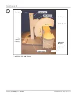
On the detector surfaces facing the patient
•
On the detector side and top covers
•
On the AC Option, if installed (see Chapter 12
CardioMD AC Option
for details).
The purpose is to detect collisions and stop motions, thereby preventing injury to the patient and
operator and damage to the equipment. When a collision sensor is activated, the detectors can only
be moved at slow speed by pressing the hand controller Collision Override button
and
a motion
button simultaneously.
2.2.2
Detectors
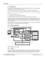
The detector assembly consists of a thallium activated sodium iodide crystal, a glass light pipe,
and an array of photomultiplier tubes (PMT’s). Gamma photons striking the crystal generate
scintillation light with an intensity proportional to the energy loss of the gamma photons. The
energy range of gamma photons accepted is from 60 keV to 170 keV. The scintillation light
falling on neighboring PMT’s also generates pulses proportional to their particular intensities. All
PMT pulses are routed to the detector EDC board (located on top of the detector) via coaxial
cables.
Note
. The crystal has a thin aluminum cover which is biased with negative high voltage.
On the CardioMD detector heads, a PMT produces an analog current relative to the light input.
This current is converted into a proportional voltage signal inside each PMT assembly. Voltage
signals from all PMT’s are combined in groups. The signal from each group is summed to four
position signals, X+, X–, Y+, Y–, and an energy signal. These five sum signals are then digitized
on the Event Digitization & Control (EDC) board. The digitized signals are integrated and
corrected on the fly, followed by X-Y position calculation and energy calculation. Note that the
EDC board only processes one event at a time, but fast enough to ensure that no information is
lost at count rates experienced in clinical use. Finally, each event is corrected for detector/system
characteristics such as spatial linearity and local energy response.
The output from the detector, that is, the corrected event position and energy information, is sent
via the FireWire control interface to the acquisition PC for imaging.
The detector assembly is shielded with lead-bronze alloy. This arrangement prevents external light
from reaching the PMT’s and charged particles from reaching the crystal. It also protects the
crystal from most of the gamma photons arriving from the side or rear of the detector. Gamma
photons are focused on the crystal by a collimator placed over the detector face. A collimator is a
honeycomb structure of lead alloy. The holes in the collimator serve to select the angle in which
gamma photons may enter. In each case, the passage of gamma photons forming a projection
image is favored, since they are not absorbed by the lead septa between the holes.
The detector automatically identifies the collimator type attached. The collimator type information
is transmitted to the acquisition computer for applying appropriate corrections.
2.2.3
Collimator
The CardioMD is designed to support LEGP and LEHR collimators.
The collimator/detector interface allows automatic detection of the collimator type attached,
ensuring that appropriate correction is applied.
CardioMD collimators are changed by hand. When not in use, collimators can be stored in the
CardioMD collimator cabinet. The CardioMD’s motion control system automatically brings the
detectors into exchange position when activated by the connected acquisition PC.
Содержание CARDIOMD
Страница 1: ...CARDIOMD SERVICE MANUAL 1MAN0158 H11 04 2005 CSIP Level 1 ...
Страница 10: ...Introduction x CardioMD Service Manual 1MAN0158 H11 04 2005 CSIP Level 1 ...
Страница 16: ...Safe Operating Practices 1 6 CardioMD Service Manual 1MAN0158 H11 04 2005 CSIP Level 1 ...
Страница 164: ...Detector Calibration Files 5 60 CardioMD Service Manual 1MAN0158 H11 04 2005 CSIP Level 1 ...
Страница 207: ...Installation 1MAN0158 H11 04 2005 CSIP Level 1 CardioMD Service Manual 8 5 Figure 8 2 System footprint with short table ...
Страница 232: ...Installation 8 30 CardioMD Service Manual 1MAN0158 H11 04 2005 CSIP Level 1 Figure 8 17 Installation template ...
Страница 328: ...Installation Procedures 9 38 CardioMD Service Manual 1MAN0158 H11 04 2005 CSIP Level 1 ...
Страница 348: ...Planned Maintenance Procedures 11 6 CardioMD Service Manual 1MAN0158 H11 04 2005 CSIP Level 1 ...
Страница 465: ......


