288
Overview of Analog I/O Slave Units
Section 6-1
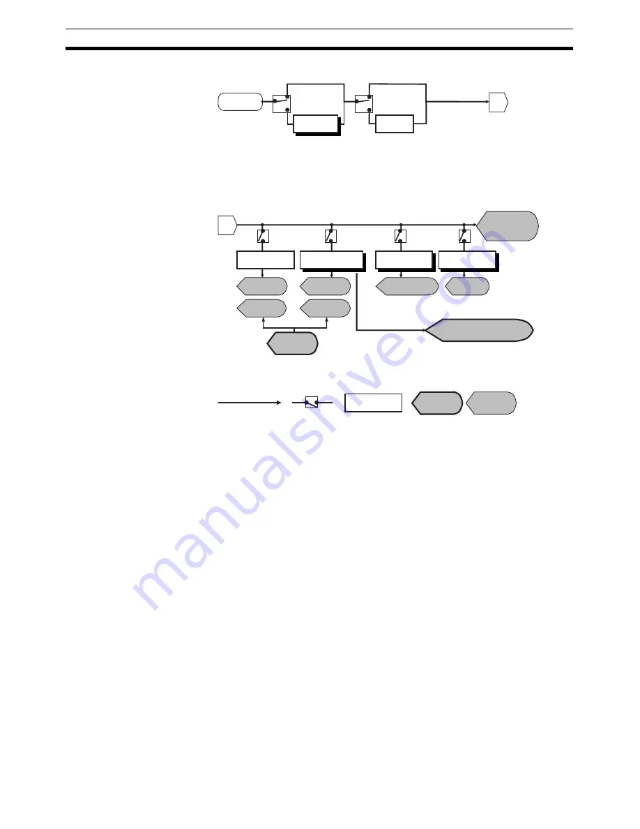
Analog processing is performed according to the following flowchart.
6-1-4
Selecting Data for Analog Input Slave Units
After performing math operations, select one out of the six resulting values to
allocate in the Master Unit, from the analog input value, peak value, bottom
value, top value, valley value, and rate of change. The selected data is
referred to as “analog data” and can be allocated in the Master Unit individu-
ally or in combination with Status Flags. The data is selected using the CX-
Integrator. For Analog Data, comparator operations with four alarm set values
can be performed (comparator function).
Input
Moving
average
Scaling
A
A
Analog input
value 1
Peak/Bottom
Top/Valley
Rate of change
Cumulated
value
Peak
value 2
Top
value 4
Rate of change
value 6
Cumulated
value
Hold Flag
Top/Valley detection timing
(allocated I/O data)
Data Flow
Selection
Conversion
processing
Allocated
I/O data
Processing
results
Bottom
value 3
Valley
value 5
Содержание CRT1 - 10-2008
Страница 2: ...CRT1 Series CompoNet Slave Units and Repeater Unit Operation Manual Revised October 2008...
Страница 3: ...iv...
Страница 5: ...vi...
Страница 9: ...x...
Страница 15: ...xvi...
Страница 23: ...xxiv Conformance to EC Directives 6...
Страница 51: ...28 Slave Unit Models Section 1 2...
Страница 123: ...100 Connecting External I O for Slave Units Section 3 6...
Страница 365: ...342 Temperature Input Units Section 7 5...
Страница 381: ...358 Expansion Unit Specifications Section 8 2...
Страница 418: ...395 Repeater Unit Section 10 2 Dimensions 42 3 50 3 1 27 5 95 mm...
Страница 419: ...396 Repeater Unit Section 10 2...
Страница 424: ...401 CX Integrator Section 11 1...
Страница 575: ...552 Current Consumption Summary Appendix D 552...
Страница 581: ...558 Index...
Страница 583: ...560 Revision History...


