Oki BV1250 Installation Guide
Revision 1.0
Page vii
List of Figures
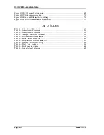
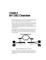
Figure 2-1: Simplified IVG network connection .......................................................................................3
Figure 3-1: Basic network configuration .................................................................................................11
Figure 3-2: Examples of undesirable network configurations .................................................................12
Figure 3-3: Sample network configuration with H.323 Gatekeeper ........................................................14
Figure 3-4: DNS options..........................................................................................................................20
Figure 3-5: Relationship of terminals to E&M/E&M-OD .......................................................................21
Figure 3-6: Up to 30 BBV1250-E&M units can be associated with a PBX ............................................22
Figure 3-7: Maximum PBX routing.........................................................................................................22
Figure 3-8: IVG and analog telephones and fax ......................................................................................23
Figure 3-9: IVG and Key Telephone System...........................................................................................23
Figure 3-10: BV1250-AP/FXS connected with PBX ..............................................................................23
Figure 3-11: BV1250-AP/FXS unit terminated with Auto Attendant .....................................................24
Figure 3-12: BV1250-AP/FXS terminated with IVR ..............................................................................24
Figure 3-13: BV1250-FXO unit connection with PBX ...........................................................................25
Figure 3-14: BV1250-FXO unit connection to PSTN .............................................................................26
Figure 3-15: BV1250-FXO unit ports divided to serve both PBX and PSTN .........................................26
Figure 3-16: DTMF Detect ......................................................................................................................29
Figure 3-17: AP/FXS Network error detection flowchart........................................................................65
Figure 3-18: Trunk Groups ......................................................................................................................82
Figure 3-19: E&M Network error detection flowchart ............................................................................92
Figure 3-20: FXO Network error detection flowchart ...........................................................................126
Figure 4-1: BV1250 chassis cover removal...........................................................................................141
Figure 4-2: Line interface board installation..........................................................................................142
Figure 4-3: E&M line interface board DIP switch locations .................................................................143
Figure 4-4: RJ connector cutouts ...........................................................................................................145
Figure 4-5: Replace unit chassis cover ..................................................................................................146
Figure 4-6: Front label placement..........................................................................................................147
Figure 4-7: Maintenance label placement..............................................................................................148
Figure 4-8: Maintenance Label on BV1250 with E&M Board..............................................................148
Figure 4-9: Base unit footprint and clearance dimensions.....................................................................149
Figure 4-10: Rack mount bracket installation........................................................................................152
Figure 4-11: Securing the unit in the rack..............................................................................................153
Figure 4-12: Rack-mount base unit positioning.....................................................................................153
Figure 4-13: Power Cable Attachment ..................................................................................................155
Figure 4-14: US and EU power cable plugs ..........................................................................................155
Figure 4-15: Earth Ground attachment ..................................................................................................157
Figure 4-16: SG common ground ..........................................................................................................157
Figure 4-17: FXS connector preparation ...............................................................................................158
Figure 4-18: AP connector preparation..................................................................................................159
Figure 4-19: Connecting a rack mounted unit .......................................................................................159
Figure 4-20: Connecting a desktop mounted unit ..................................................................................159
Figure 4-21: Connecting a unit to PBX analog Loop Start trunk board ................................................160
Figure 4-22: FXS connector preparation ...............................................................................................161
Figure 4-23: FXO connector preparation...............................................................................................161
Figure 4-24: Connecting a unit directly to PSTN ..................................................................................162
Figure 4-25: Connecting a unit to PBX analog Subscriber Line board .................................................162
Figure 4-26: E&M unit connector orientation and label placement.......................................................163
Figure 4-27: Connecting E&M to PBX E&M Tie Trunk interface .......................................................165
Figure 4-28: E&M-OD connector preparation.......................................................................................166
Figure 4-29: E&M-OD connector wiring ..............................................................................................167
Figure 4-30: Cable restraint installation ................................................................................................168
Figure 4-31: RS-232C pin configuration ...............................................................................................169
Содержание BV1250
Страница 1: ...BV1250 Internet Voice Gateway INSTALLATION GUIDE Oki Electric Industry Co Ltd...
Страница 2: ......
Страница 12: ...INTRODUCTION Oki BV1250 Installation Guide Page 2 of 334 Revision 1...
Страница 18: ...OVERVIEW Oki BV1250 Installation Guide Page 8 of 334 Revision 1 0...
Страница 20: ...PLANNING Oki BV1250 Installation Guide Page 10 of 334 Revision 1 0...
Страница 142: ...FXO WORKSHEETS Oki BV1250 Installation Guide Page 132 of 334 Revision 1 0...
Страница 144: ...PHYSICAL INSTALLATION Oki BV1250 Installation Guide Page 134 of 334 Revision 1 0...
Страница 184: ...LOGICAL INSTALLATION Oki BV1250 Installation Guide Page 174 of 334 Revision 1 0...
Страница 270: ...APPENDICES Oki BV1250 Installation Guide Page 260 of 334 Revision 1 0...
Страница 280: ...Oki BV1250 Installation Guide APPENDICES Revision 1 0 Page 270 of 334 Sample Network IP Addressing Hierarchy...
Страница 284: ...Oki BV1250 Installation Guide APPENDICES Revision 1 0 Page 274 of 334 Sample Network Numbering Plan...
Страница 329: ...Oki BV1250 Installation Guide APPENDICES Revision 1 0 Page 319 of 334...
Страница 343: ...Oki BV1250 Installation Guide APPENDICES Revision 1 0 Page 333 of 334...
Страница 344: ...APPENDICES Oki BV1250 Installation Guide Page 334 of 334 Revision 1 0...


