


69rlq62d-f714peg4 * Memec (Headquar
ter
s) - Unique
Tec
h,
Insight,
Impact
MAR
VELL CONFIDENTIAL,
UNDER ND
A# 12101050
69rlq62d-f714peg4 * Memec (Headquar
ter
s) - Unique
Tec
h,
Insight,
Impact
MAR
VELL CONFIDENTIAL,
UNDER ND
A# 12101050
69r
lq62d-f714peg4 * Memec (Headquar
ters) - Unique
T
ech, Insight, Impact * UNDER ND
A# 12101050
MAR
VELL CONFIDENTIAL - UNA
UTHORIZED DISTRIB
UTION OR USE STRICTL
Y PR
OHIBITED
PXA300 Processor and PXA310 Processor
Vol. I: System and Timer Configuration Developers Manual
Doc. No. MV-TBD-00 Rev. A
CONFIDENTIAL
Copyright © 12/13/06 Marvell
Page 452
Document Classification: Proprietary Information
December 13, 2006
Not approved by Document Control. For review only.
17.2
Features
The JTAG interface has the following features and conformities:
•
JTAG interface that conforms to the IEEE Std. 1149.1 – 1990, IEEE Std. 1149.1a-1993, Standard Test
Access Port and Boundary-Scan Architecture.
•
Support for hardware/software debug
Refer to the IEEE Std. 1149.1 for an explanation of the terms used in this section and for a complete description
of the TAP controller states.
17.3
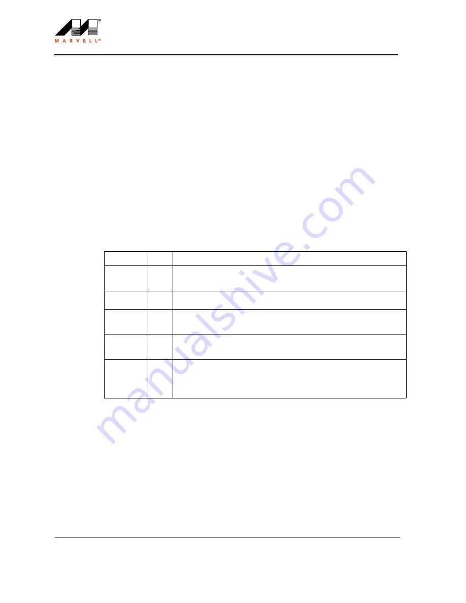
Signal Descriptions
The JTAG interface is controlled through five dedicated TAP controller pins: TDI, TMS, TCK, nTRST, and
TDO. These pins are described in
17.4
Operation
This section describes the TAP controller, hardware connection, JTAG instruction set (Instruction register),
test-data registers, and data-specific register.
17.4.1
TAP Controller Reset
The JTAG interface includes a TAP controller state machine. To force the TAP controller into the correct state at
powerup, the nTRST pin can be asserted low, or the TMS pin can be held high for five TCK cycles. Marvell
recommends that nTRST be driven from low to high either before or at the same time as the hardware nRESET
Table 17-1. TAP Controller Pin Definitions
Name
Type
Description
TCK
Input
Clock input for the TAP controller, Instruction register, and test data registers. Limited
to 3.25 MHz maximum frequency for Boundary Scan register, and 13 MHz for all
other registers. There is no minimum.
TMS
Input
Controls operation of the TAP controller. TMS is sampled on the rising edge of TCK.
The TMS input is pulled high when not being driven.
TDI
Input
Serial data input to the instruction and test data registers. Data at TDI is sampled on
the rising edge of TCK. TDI is pulled high by an internal pullup resistor when not
being driven.
TDO
Output
Serial data output. Data at TDO is clocked out on the falling edge of TCK. It provides
an inactive (high-Z) state during non-shift operations to support parallel connection of
TDO outputs at the board or module level.
nTRST
Input
Provides asynchronous initialization of the JTAG test logic. Assertion of this pin puts
the TAP controller in the TEST_Logic_Reset state. An external source must drive
nTRST either before or at the same time as the hardware nRESET pin for correct
TAP controller and device operation. The nTRST input is pulled high by an internal
pullup resistor when not being driven.


