62
Id.-Nr.: 1556.212 .1-07
Appendix: Tutorial - Creating a visualization
19
Appendix: Tutorial - Creating a
visualization
Building on the tutorial "Creating an IEC project in MotionCenter", a visualization is
created in this tutorial. The panel connected to the control shows the current value of
the variable X configured in the MotionCenter.
Requirements for this tutorial:
•
The sample project from the tutorial "Creating an IEC project in MotionCenter"
was developed and is located on the control as a boot project (meaning it is au-
tomatically started during the startup of the control).
•
A stationary panel is connected to the control.
19.1
Selecting variables for visualization
In order to be able to access IEC variables that are set up in MotionCenter during the
creation of visualization project and during the design of masks, they must first be ex-
plicitly selected. To do so, the object "Symbol Configuration" must be created under
the node
Application
via right-click and
dd Object...
. The variables can be selected
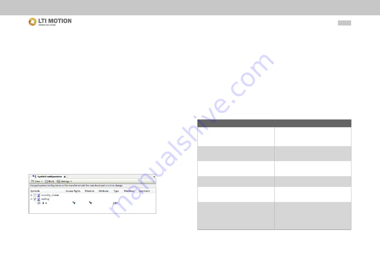
in the symbol configuration by activating the check boxes. To do so, however, the
project must first be built through
Build > Build
(or short-cut key F11 or icon on the
tool bar) to update the variables contained in the project.
Fig. 19.41:
Symbol configuration
In the Symbol configuration window, select the variables that need to be used for the
visualization.
In order to create symbol entries for the variables - as you have just configured it -
you must rebuild the project. This is done again via
Build > Build
(or shortcut key
F11 or icon on the tool bar).
19.2
Adding the visualization to the control
configuration
Now, the corresponding panel must be inserted into the project. This is done by right
clicking on the node
Panel
in the project tree and selecting "Add Device...". The de-
vice selection dialog opens from where the operating device connected to the control
is selected and added. After that, the dialogue can be closed.
The visualization configuration needs to be carried out next. To do so, open the con-
text menu of the node
Visualisierung
and attach a visualization via
Add Object... >
Visualization...
.
This opens a dialog where the following parameters can be set:
Parameters for Visualization
Parameters
Meaning
Project Path
The path where the visualization application
has been created is shown here. By clicking
on the path, the respective directory can be
opened.
Save relative path
When this option has been activated, the
project path is saved relative to the Mo-
tionOne 3 project.
Description
The description is loaded onto the control dur-
ing the download and can later be displayed
by online tools as additional information.
Visualization System
Indicates which visualization system is used
by the visualization application.
Primary Device
The visualization application is created for this
device. Amongst others the resolution of the
visualization application depends of that.
Additional devices
The application is created for a specific dis-
play device, but can also be utilized on addi-
tional other display devices. To do so, during
the download the visualization application is
also downloaded for the devices that are se-
lected here.
The values set by default can be adopted. The visualization device is appended via
"Add".


