Alarm code
51
Abnormal Inverter current sensor.
•
The RUN indicator flashes and the ALARM indication is displayed on the remote control switch.
•
The unit no., the alarm code and the unit code are alternatively displayed in the temperature setting section and the unit
no. and alarm code are displayed on the outdoor unit's PCB1 display.
* In the case that the current transformer anomaly (0A detection) occurs three times in thirty minutes, this alarm is
indicated on the third time (retry operation is carried up to the second time the anomaly is detected)
Activation condition:
When the compressor frequency is maintained between 15 and 18 Hz after the compressor is started, one of the absolute
running current values detected by the current transformer in each phase U+, U-, V+ and V- is equal or less than 1.5 A.
l
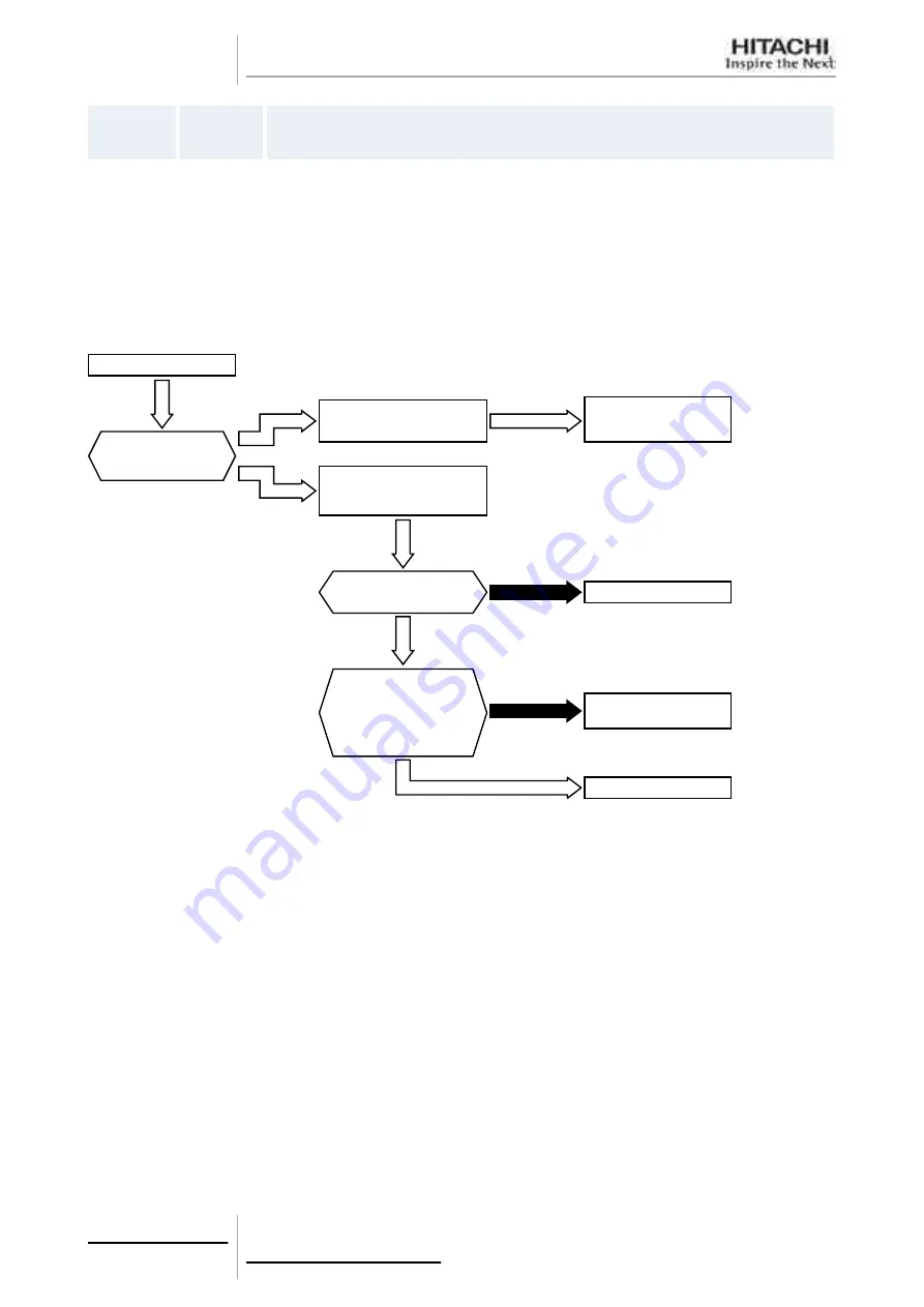
Is output of
PCB2 correct? *2)
l
Or is output of voltage
between U and V,
V and W, W and U
correct?
Replace Comp.
Restart operation.
Abnormal
Faulty PCB2
and replace PCB2. *2)
Compressor stops
immediately. (nearly 18Hz)
Compressor is not
operated.
P17 is appeared. *1)
How is compressor
operation when
restarted?
Is the coil resistance
of compessor normal?
Normal
Check PCB2 or
the transistor module.
Abnormal
Normal
Replace PCB2. *2)
PCB1: Control PCB in Outdoor Unit
PCB2: Inverter PCB
*1): P17 is displayed on the 7-segment display of the outdoor unit PCB1.
*2): Carry out the high voltage discharge before Inverter parts are checked or replaced, refer to
, see on page 267
.
8 Troubleshooting
222
SMGB0065 rev. 1 - 12/2010


