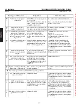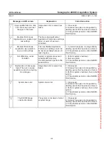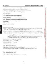
CHAP
. 15
GE Healthcare
Senographe 2000 D Acquisition System
REV 1
OM 5179217–1–100
167
2.
RADIATION AND FILTER INFORMATION
2-1
Radiation Reference Axis
Conforming to standard mammography practice, the radiation reference axis is directed at the chest
wall edge of the digital detector; radiation is shielded so that there is no radiation directed behind the
chest wall.
2-2
Technical Leakage Factor
With respect to radiation regulation, the tube housing and the collimator are in compliance with DHHS
21 CFR1020:
Technical leakage factors applicable: 49 kV at 2 mA.
2-3
Filters and Anode Tracks
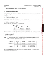
Maximum current for each track/focal spot configuration:
TRACK
FOCAL SPOT
Mo
Rh
Large
100 mA max.
75 mA max.
Small
40 mA max.
40 mA max.
The filters are installed on a disk driven by a stepping motor which moves from one filter to the other.
Two different filters are supplied:
D
Molybdenum: 0.03 mm,
D
Rhodium: 0.025 mm,
Note:
The Column electronics control the filters according to operator requirements in manual
mode, or to software requirements in AOP mode.
TARGET
VOLTAGE
(kV)
FILTER
HALF-VALUE LAYER
Molybdenum
30
0.03 Mo
0.3 mm Al minimum
30
0.025 Rh
0.35 mm Al minimum
Rhodium
30
0.025 Rh
0.4 mm Al minimum
The minimum filtration permanently installed in the useful beam is 0.008 mm Al (8
μ
m Al) at 30 kV
(corresponding to 0.69 mm Beryllium).
FOR
TRAINING
PURPOSES
ONLY!
NOTE:
Once
downloaded,
this
document
is
UNCONTROLLED,
and
therefore
may
not
be
the
latest
revision.
Always
confirm
revision
status
against
a
validated
source
(ie
CDL).

