X90 mobile modules
72
X90 mobile system User's manual V 1.20 - Translation of the original manual
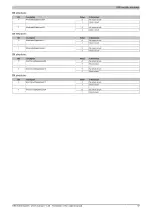
5.2.1.12.7.6 Counter functions - Configuration of latch events
Name:
cfgLatchModeUnit01
cfgLatchModeUnit03
These registers define on which states of A, B, R, E or D, F, R, E the counter values of the counters are applied to
the associated latch registers. When applied, the associated latch event counter is incremented.
Data type
Values
UINT
See the bit structure.
Bit structure of cfgLatchModeUnit01:
Bit
Description
Value
Information
0
Disabled
0
Counter 01: Input 01 high level
1
Enabled
0
Disabled
1
Counter 01: Input 02 high level
1
Enabled
0
Disabled
2
Counter 01: Input 03 high level
1
Enabled
0
Disabled
3
Counter 01: Input 04 high level
1
Enabled
0
Disabled
4
Counter 01: Input 01 low level
1
Enabled
0
Disabled
5
Counter 01: Input 02 low level
1
Enabled
0
Disabled
6
Counter 01: Input 03 low level
1
Enabled
0
Disabled
7
Counter 01: Input 04 low level
1
Enabled
0
Single shot
1
Continuous
2 to 254
Reserved
8 to 15
Latch mode of counter 01
255
Disabled
Bit structure of cfgLatchModeUnit03:
Bit
Description
Value
Information
0
Disabled
0
Counter 03: Input 05 high level
1
Enabled
0
Disabled
1
Counter 03: Input 06 high level
1
Enabled
0
Disabled
2
Counter 03: Input 07 high level
1
Enabled
0
Disabled
3
Counter 03: Input 08 high level
1
Enabled
0
Disabled
4
Counter 03: Input 05 low level
1
Enabled
0
Disabled
5
Counter 03: Input 06 low level
1
Enabled
0
Disabled
6
Counter 03: Input 07 low level
1
Enabled
0
Disabled
7
Counter 03: Input 08 low level
1
Enabled
0
Single shot
1
Continuous
2 to 254
Reserved
8 to 15
Latch mode of counter 03
255
Disabled


