X90 mobile modules
X90 mobile system User's manual V 1.20 - Translation of the original manual
309
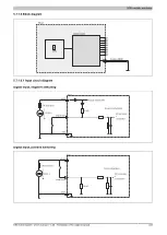
5.6.1.7.1 Input circuit diagram
Digital input, negative switching
10 kΩ
12/24 V
Status
Current
Source configuration
Relay active
Digital input
GND
ECU
Vcc
Supply voltage Vs1
10 A slow-blow
Digital input, positive switching
12/24 V
(sensor power supply)
Digital output
10 kΩ
Digital input
GND
Status
Current
Status
Current
Relay active
Sink configuration
ECU
Vcc
Supply voltage Vs1
10 A slow-blow
Digital output
Sensor power supply (permanently on)
Digital input
Sensor input (positive switching)
Note that in the event of power failure or if the enable relay is cut off, then the power supply for the sensor is also
cut off. This is because the module is supplied with power via the freewheeling diode, which can result in damage.
It is therefore recommended to provide power to positive-switching inputs via an output.


