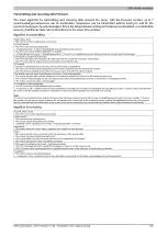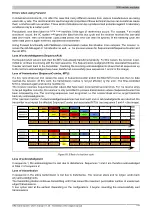
X90 mobile modules
X90 mobile system User's manual V 1.20 - Translation of the original manual
237
Ground loops can occur when the module and sensor are mounted far apart. If necessary, isolated mounting must
be performed using an isolated adhesive mounting plate.
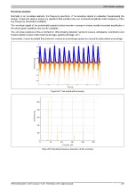
The resonant frequency is reduced by additional elements such as an isolation flange, collar screw, magnetic clamp
and probe tip positioned between the coupling surfaces. The coupling becomes softer using these elements. These
differences can be clearly seen in the frequency response diagram
Different frequency responses of the relative voltage transfer factor are illustrated in the image below.
Deviation in sensitivity
3 dB
0
10
100
1,000
10,000
Frequency [Hz]
Coupling via holding magnet
Coupling via probe tip
Coupling via screw connection
Figure 66: Attenuation of the different types of sensor mounting
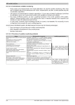
The choice of mounting is influenced by the resonance frequency and temperature. The following table shows how
strongly these influences impact on the different mounting methods.
Resonant frequency
Temperature
Stud
Instant adhesive
Beeswax
Double-sided adhesive tape
Magnetic clamp
Probe tip
Effects on the installation methods:
High
Medium
Low
Installation procedure
Depending on the conditions of the location, sensors can be screwed directly onto the surface of the object to
be measured.
STEP 1:
As smooth and flat a surface as possible is needed to mount the sensors. The required size depends
on the sensor; see the data sheet.
STEP 2:
An M8 blind hole is needed to attach the B&R sensors.
STEP 3:
To further improve the transfer performance, a thin layer of silicon grease can be applied between the
object surface and the sensor mounting surface. This is not necessary in most cases and is only useful when
measuring particularly high-frequency vibrations.
STEP 4:
The sensor should be tightened by approx. 8 Nm when using the M8x1 screw thread. If necessary, the
sensor can additionally be secured with adhesive.


