X90 mobile modules
X90 mobile system User's manual V 1.20 - Translation of the original manual
249
Envelope
When you look at the various causes of oscillations, it becomes clear that they primarily come from 2 sources:
1. Imbalance and misalignment
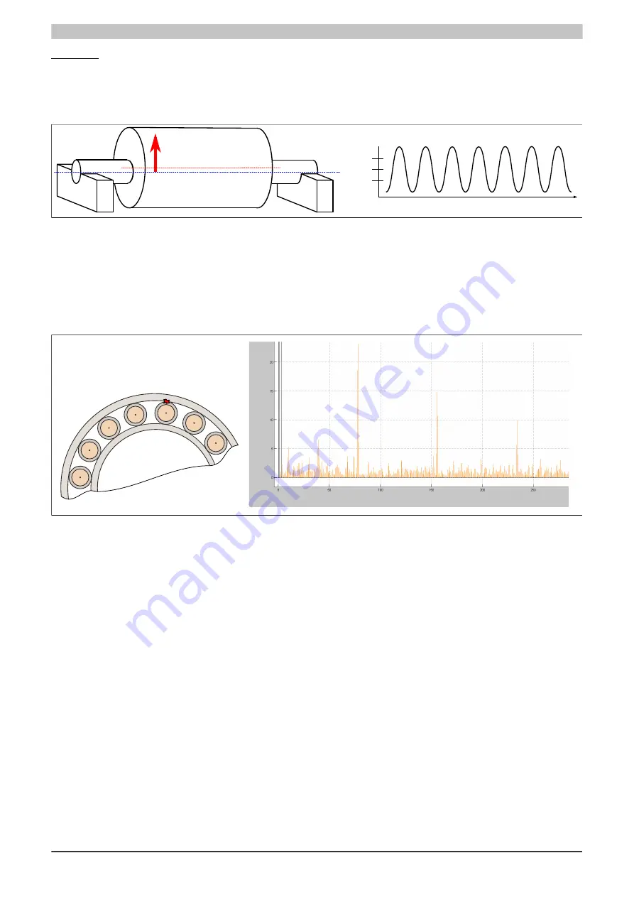
Imbalance and problems with alignment lead to predominantly harmonic, sinusoidal oscillations.
0
+
-
Mid-axis
Middle of cylinder
Imbalance
Amplitude
Time
Figure 81: Imbalance - Harmonic oscillation
2. Impacts
Many types of machine damage can result in oscillations that cause the structure of the machine or adjacent
machine parts to vibrate at their natural frequency. Impact-related causes of this are a result of corrosion, a rotor
brushing up against the machine housing or roller bearing/gearing damage to the gears.
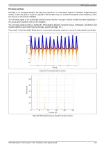
In the case of roller bearing damage, impact occurs when either the rolling elements roll over damage on the inner
or outer track or when one of the rolling elements themselves is damaged.
Frequency [Hz]
Amplitude
[mg]
Figure 82: Bearing damage - FFT of envelope signal
This kind of impact can be compared to a clapper hitting a bell. If the bell is struck 2x per second, it vibrates at
its natural frequency and not 2 Hz. The natural frequency is determined by the constructive design and material
properties. As with any sound boxes, mounting also factors into this.
If the damage is to the roller bearing track, every shock pulse will lead to a corresponding reaction in the vibrating
system. It is only practical to measure the sum of all pulses, i.e. the total signal.
In the case of damage to roller bearings, the bearing rings are the first to start vibrating.
Analyzing oscillations
Oscillations are transmitted in the machine as waves and can be measured on the machine's surface. A prerequi-
site, of course, is that a path is available for the sound transport, i.e. there are no sound-absorbing border crossings
such as air, rubber, etc. between the roller bearing and sensor.
This signal can be measured on the surfaces of the machine by means of an accelerometer. The signal is made
up of a variety of oscillations and impacts that overlap each other. When considering the time signal in this way, it
is easy to see that allocating individual frequencies is difficult, if not impossible.
Using a Fast Fourier transform, this time signal can be converted to give the natural frequency of the system.
These are in the high-frequency range. The rotor frequency and its harmonic frequency are clearly identifiable as
the dominant frequency portion.
The rollover frequencies of the roller bearings are between 15 and 70 Hz at a speed of approximately 600 rpm,
depending on the bearing.
In particular, shock pulses of a lower intensity, as they are when damage first begins, can barely be noticed or
assessed. It is only when there is advanced damage to bearings that signal peaks can be clearly observed.


