X90 mobile modules
X90 mobile system User's manual V 1.20 - Translation of the original manual
205
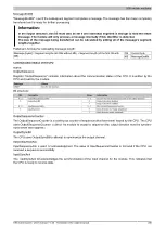
MessageEndBit
"MessageEndBit" is set if the subsequent segment completes a message. The message has then been completely
transferred and is ready for further processing.
Information:
In the output direction, this bit must also be set if one individual segment is enough to hold the entire
message. The module will only process a message internally if this identifier is detected.
The size of the message being transferred can be calculated by adding all of the message's segment
lengths together.
Flatstream formula for calculating message length:
CB
Control byte
Message [bytes] = Segment lengths (all CBs without ME) + Segment length (of the first CB with
ME)
ME MessageEndBit
Communication status of the CPU
Name:
OutputSequence
Register "OutputSequence" contains information about the communication status of the CPU. It is written by the
CPU and read by the module.
Data type
Values
USINT
See the bit structure.
Bit structure:
Bit
Description
Value
Information
0 - 2
OutputSequenceCounter
0 - 7
Counter for the sequences issued in the output direction
0
Output direction disabled
3
OutputSyncBit
1
Output direction enabled
4 - 6
InputSequenceAck
0 - 7
Mirrors InputSequenceCounter
0
Input direction not ready (disabled)
7
InputSyncAck
1
Input direction ready (enabled)
OutputSequenceCounter
The OutputSequenceCounter is a continuous counter of sequences that have been issued by the CPU. The CPU
uses OutputSequenceCounter to direct the module to accept a sequence (the output direction must be synchro-
nized when this happens).
OutputSyncBit
The CPU uses OutputSyncBit to attempt to synchronize the output channel.
InputSequenceAck
InputSequenceAck is used for acknowledgment. The value of InputSequenceCounter is mirrored if the CPU has
received a sequence successfully.
InputSyncAck
The InputSyncAck bit acknowledges the synchronization of the input channel for the module. This indicates that
the CPU is ready to receive data.


