


Sigma II User’s Manual
Chapter 5: Parameter Settings and Functions
5-144
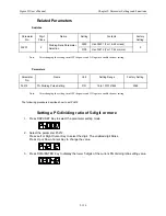
Refer to the following table for the Hall sensor signal patterns.
The Hall sensors are set according to the motor phase order selection in parameter
Pn080.1.
The processing at reading the Hall sensor signals has also been improved as follows.
If all the Hall sensor signals are 0 or 1 when the Hall sensors are connected, these
signals are ignored.
• However, if it occurs two times consecutively, the alarm A.C2 occurs.
• If U-phase edge does not activate two times continuously, it is not recognized as U-
phase edge.
• The angle for phase detection error is changed from 30 degrees to 40 degrees.
(The error of angle at installation is added to the maximum error of the angle when
the power is turned ON.)
Hall sensor
signal pattern
(UVW)
Signals
U-phase
V-phase
W-phase
0
L
L
L
1
L
L
h
2
L
h
L
3
L
h
h
4
h
L
L
5
h
L
h
6
h
h
L
7
h
h
h
Summary of Contents for SGMAH
Page 1: ...Sigma II Series Servo System User s Manual...
Page 2: ......
Page 4: ...ii This page intentionally left blank...
Page 6: ...iv This page intentionally left blank...
Page 10: ...Sigma II User s Manual Table of Contents Preface viii Notes...
Page 17: ...Sigma II User s Manual Table of Contents Preface xv C 6 Torque Control Mode C 9...
Page 18: ...Sigma II User s Manual Table of Contents Preface xvi...
Page 38: ...Sigma II User s Manual Chapter 2 Installation 2 10 NOTES...
Page 472: ...Sigma II User s Manual Appendix C Examples of Standard Connections C 10 Notes...
Page 487: ......