Sigma II User’s Manual
Chapter 5: Parameter Settings and Functions
5 - 26
5.2.4
Sequence I/O Signals
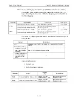
Sequence I/O signals are used to control servo amplifier operation. Connect these
signal terminals as required.
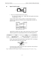
Input Signal Connections
Connect the sequence input signals as shown below.
Note:
Provide a separate external I/O power supply; the servo amplifier does not have an internal 24V
power supply.
•
External power supply specifications: 24V ±1 V
DC
, 50mA minimum.
Yaskawa recommends using the same type of external power supply as that used for output circuits.
The function allocation for sequence input signal circuits can be changed.
See
5.3.3 Input Circuit Signal Allocation
for more details.
The external power supply input terminal is common to sequence input signals.
Contact input signals:
/S-ON (CN1-40)
/P-CON (CN1-41)
P-OT (CN1-42)
N-OT (CN1-43)
/ALM-RST (CN1-44)
/P-CL (CN1-45)
/N-CL (CN1-46)
Input +24VIN CN1-47
External I/O Power Supply Input
Speed/Torque Control,
Position Control
I/O power
supply
CN1-47
CN1-40
CN1-41
CN1-42
CN1-43
CN1-44
CN1-45
CN1-46
0V
+ 24V
Servo Amplifier
Photocoupler
Host controller
+24V
IN
/S-ON
/P-CON
P-OT
N-OT
/ALM-RST
/P-CL
/N-CL
3.3k
Ω
Servo amplifier
I/O power supply
Connect an external I/O power supply
+24V
+24V
in
CN1-47
Summary of Contents for SGMAH
Page 1: ...Sigma II Series Servo System User s Manual...
Page 2: ......
Page 4: ...ii This page intentionally left blank...
Page 6: ...iv This page intentionally left blank...
Page 10: ...Sigma II User s Manual Table of Contents Preface viii Notes...
Page 17: ...Sigma II User s Manual Table of Contents Preface xv C 6 Torque Control Mode C 9...
Page 18: ...Sigma II User s Manual Table of Contents Preface xvi...
Page 38: ...Sigma II User s Manual Chapter 2 Installation 2 10 NOTES...
Page 472: ...Sigma II User s Manual Appendix C Examples of Standard Connections C 10 Notes...
Page 487: ......


