Sigma II User’s Manual
Chapter 5: Parameter Settings and Functions
5-85
Connecting Regenerative Resistors
The method for connecting regenerative resistors is shown below.
Servo Amplifier Capacity of 400W or Less
Connect an external regenerative resistor between the servo amplifier’s B1 and B2
terminals.
Servo Amplifier Capacity of 0.5 to 5.0kW
Disconnect the wire between the servo amplifier’s B2 and B3 terminals and connect
an external regenerative resistor between the B1 and B2 terminals.
Servo Amplifier Capacity of 6.0kW or More
Servo amplifiers with capacities of 6.0kW or more do not have built in regenerative
resistors, so an external unit is required. The following regenerative resistor units
are designed to meet this need. Parameter Pn600 must be set to identify the external
unit’s capacity (with appropriated derating).
Use one of the following resistor unit for the large capacity amplifiers (22-55kW).
Servo Amplifier
Applicable Regenerative
Resistor Unit
Resistance
Ω
Specifications
SGDH-60AE
JUSP-RA04
6.25
25
Ω (
220W)
×
4 resistors in parallel
SGDH-75AE to 1EAE
JUSP-RA05
3.13
25
Ω (
220W)
×
8 resistors in parallel
SGDH-60DE to 75DE
JUSP-RA18
18
18
Ω (
220W)
×
4 resistors in series-parallel
SGDH-1ADE to 1EDE
JUSP-RA19
14.25
28.5
Ω (
220W)
×
8 resistors in series-parallel
Servopack Model SGDH-
2BDE
3ZDE
3GDE
4EDE
5EDE
Regenerative Resistor Unit JUSP
RA12
RA13
RA14
RA15
RA16
Resistance
9
Ω
6.7
Ω
5
Ω
4
Ω
3.8
Ω
Resistance Capacity
3600W
3600W
4800W
6000W
7200W
Allowable Load Moment of Inertia
5 times the load moment of inertia at motor shaft.
Allowable Duty
2% ED at maximum speed and torque deceleration.
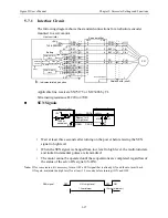
Servo amplifier
B1
B2
Regenerative resistor*
*The user must provide the regenerative resistor.
Servo amplifier
Regenerative resistor*
Be sure to take out the lead wire
between the B2 and B3 terminals.
*The user must provide the regenerative resistor.
B3
B2
B1
Summary of Contents for SGMAH
Page 1: ...Sigma II Series Servo System User s Manual...
Page 2: ......
Page 4: ...ii This page intentionally left blank...
Page 6: ...iv This page intentionally left blank...
Page 10: ...Sigma II User s Manual Table of Contents Preface viii Notes...
Page 17: ...Sigma II User s Manual Table of Contents Preface xv C 6 Torque Control Mode C 9...
Page 18: ...Sigma II User s Manual Table of Contents Preface xvi...
Page 38: ...Sigma II User s Manual Chapter 2 Installation 2 10 NOTES...
Page 472: ...Sigma II User s Manual Appendix C Examples of Standard Connections C 10 Notes...
Page 487: ......


