Parameter Description
VD300 Series Inverter User Manual
- 128 -
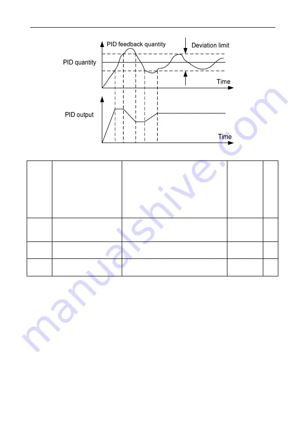
Fig 6.8-3 PID deviation limit diagram
P08.16
PID Preset Output Mode
0: No preset output mode
1: Output according to holding time
2: Output when PID feedback<
switchover threshold
3: Output when PID feedback>
switchover threshold
4: Terminal switchover
0
◎
P08.17
PID Preset Output Value
0.0%~100.0% (as frequency command
relative to max output frequency
P00.07)
10.0%
○
P08.18
PID Preset Output Value
Holding Time
0.00s~600.00s
0.50s
○
P08.19
PID
Preset Output
Switchover Threshold
0.0%~100.0% (relative to PID command
value)
50.0%
○
When P08.16 set to non-zero, namely enable PID preset mode. Appropriate setting preset frequency
preset holding time of PID preset frequency, or preset output switchover threshold, to avoid the
inverter start initial feedback and command deviation limits and make the PID regulator saturation,
can make the closed-loop regulating quickly into a stable stage and no obvious overshoot or
oscillation.
After the PID run, frequency accelerate to PID preset point according to acceleration/deceleration
time, and will keep run at the frequency point until it doesn’t meet the PID preset output retention
condition as in P08.16 set, then run according to PID regulator output. As below diagram P08.16 set
as 1:
Summary of Contents for VD300 Series
Page 2: ......


