


77
The rod actuates the switch 12 (see figure 61) installed in the intermediate and rear
cross-axle differential lock switch housing, herein indicators installed on the dashboard flash.
When closing the switch valve, pneumatic chamber is vented to atmosphere, air is dis-
charged, and the mechanism returns to its initial position under the spring force, indicator lamps
flash out.
After maintenance involving disassembly or replacement of locking mechanism parts,
adjust it. To do that, cock the axle, brake one drum and rotating the other drum, lock the axle shaft
with the differential carrier by feeding the air to the pneumatic chamber.
Screw the rod travel stop 5 against its contact with the rod butt, switch off the differen-
tial lock, screw the stop one more torque and lock it with the nut 6 at 49.0-60.8 Nm (5.0-6.2 kgfm)
torque.
4.2.6.3 Front axle main gear differs from the rear axle main gear by the drive flange.
Bushing 19 with a cover 20 is installed on the front end of the front axle pinion shaft, and flange
21 is installed on the rear end (see figure 59). Rear axle main gear has a flange from the conical
pinion side. The opposite side of the shaft can have no splines.
Axle crankcases 10 (are shown in figure 60) are combined, consist of cast medium part
and tubular housings of differential axles pressed in it. The axle shafts are off-loaded; axle con-
nection with the boss is spline-type.
4.2.6.4 Truck front axle
is driving, controlled. Construction of the king pin assembly is
shown in figure 63. Torque to the front driving wheels is transferred through the axle shafts and
the constant velocity joints (see figure 64).
For reliable and long-term operation of the driving axles use lubricants described in the
Lubricants and Hydraulic Fluids Charts and maintain the proper level in the crankcases. To re-
place lubricant in the front differential axle joints, remove the wheel, brake drum with the boss,
brake calliper, stub axle. Clean the lubricant and wash constant velocity joints parts.
If it is necessary to disassemble the ball unit from the front axle crankcase, use the puller
bolts from the big tool kit. To do that, install them in the screw-threaded bores of the ball unit
flange and torqueing them evenly, disconnect the ball unit root and the axle shaft housing.
Check the tightening of main gear fixation bolts to the axle case regularly. Bolts loosen-
ing leads to crankcase bend.
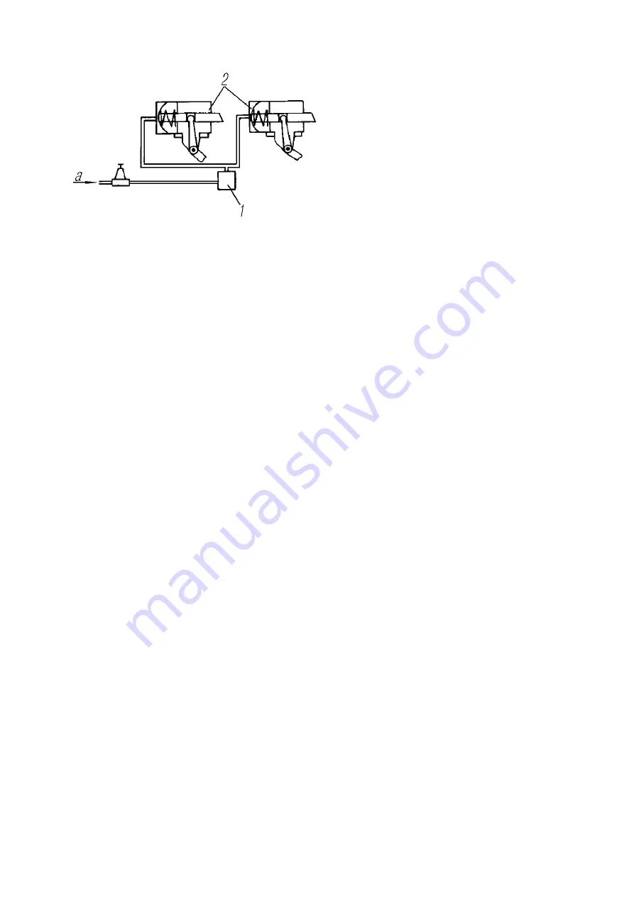
1-Solenoid valve of the intermediate and
rear axle cross-axle differential locks; 2-
switches of the intermediate and rear axle
cross-axle differential locks; a-from the tank
Figure 62 - Pneumatic Control Scheme
of the Cross-Axle Differential Lock
Summary of Contents for 4320M
Page 1: ...URAL 4320М TRUCK and its Modifications ...
Page 106: ......
Page 110: ......
Page 159: ...156 Figure 123 Engine Electronic Control Unit Wiring Scheme ...
Page 165: ......
Page 167: ......
Page 173: ......
Page 177: ...Figure 140 Installation of left and right side safety devices 171 ...
Page 201: ......
Page 203: ......
Page 205: ......
Page 207: ......
Page 209: ......
Page 212: ......
Page 214: ......
Page 216: ......
Page 218: ......
Page 220: ......
Page 222: ......
Page 224: ......
Page 226: ......
Page 228: ......
Page 230: ......
Page 232: ......
Page 234: ......
Page 236: ......
Page 238: ......
Page 240: ......
Page 242: ......
Page 244: ......
Page 246: ......
Page 248: ......
Page 250: ......
Page 252: ......
Page 254: ......
Page 256: ......
Page 257: ...223 ...
Page 259: ......
Page 315: ...280 ...
Page 317: ......