4) Uniformly apply sealant (SUZUKI BOND
NO. 1215, 99000-31110) to mating surface
of lower case.
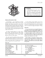
Extension Case
1) Check to ensure that knock pins are
fitted.
Fig. 13-77
Fig. 13-79
5) Install upper case to lower case by matching
3 shift forks with 3 grooves in synchronizer
sleeve on main shaft respectively.
Fig. 13-78 Shift forks
grease (SUZUKI SUPER GREASE
A 99000-25010) to oil seal lip.
3) Clean surface of extension case to mate
with transmission case and uniformly apply
sealant (SUZUKI BOND No. 1215,
31110).
Fig.
6) Tighten case bolts to specification.
Tightening torque
kg-m
lb-ft
for transmission
case bolts
18
28 1.8
2.8 13.5 20.0
4) Make sure that 3 shift shafts are in neutral
position as shown in Fig. 13-23.
5) Install extension case to transmission case.
6) Tighten case bolts to specification.
Tightening torque
kg-m
lb-ft
for extension case
bolts
18
28 1.8
2.8 13.5
20.0
13-23
Summary of Contents for Samurai 1986
Page 1: ......
Page 9: ...0 9...
Page 10: ...0 6...
Page 11: ...0 7...
Page 12: ...0 8...
Page 13: ...0 9...
Page 14: ...0 10...
Page 15: ...0 11...
Page 19: ...1 2...
Page 20: ...1 3...
Page 119: ...r a l I 29 Fig 4 1 1 Carburetor exploded view 4 3...
Page 120: ...N Fig 4 l 2 Carburetor cross section 4 4...
Page 154: ......
Page 155: ...T c c x 5 5 3...
Page 347: ...Fig 17 1 34 17 12...
Page 348: ...17 13...
Page 353: ...Fig 17 2 12 17 18...
Page 354: ...17 19...
Page 360: ...Fig 17 3 19 Fig 17 3 20 Fig 17 3 21 5 Fig 17 3 23 Ci Fig 17 3 24 Fig 17 3 22 17 25...
Page 424: ...Fig 19 6 1 19 38 19 6 PARKING BRAKE...
Page 448: ...20 13...
Page 450: ...21 2...
Page 475: ...22 5...
Page 476: ...22 6...
Page 477: ...22 7...
Page 478: ...22 8...
Page 479: ...22 9...
Page 480: ......
Page 481: ......


