Introduction 2
CG635 Synthesized Clock Generator
Front-Panel Overview
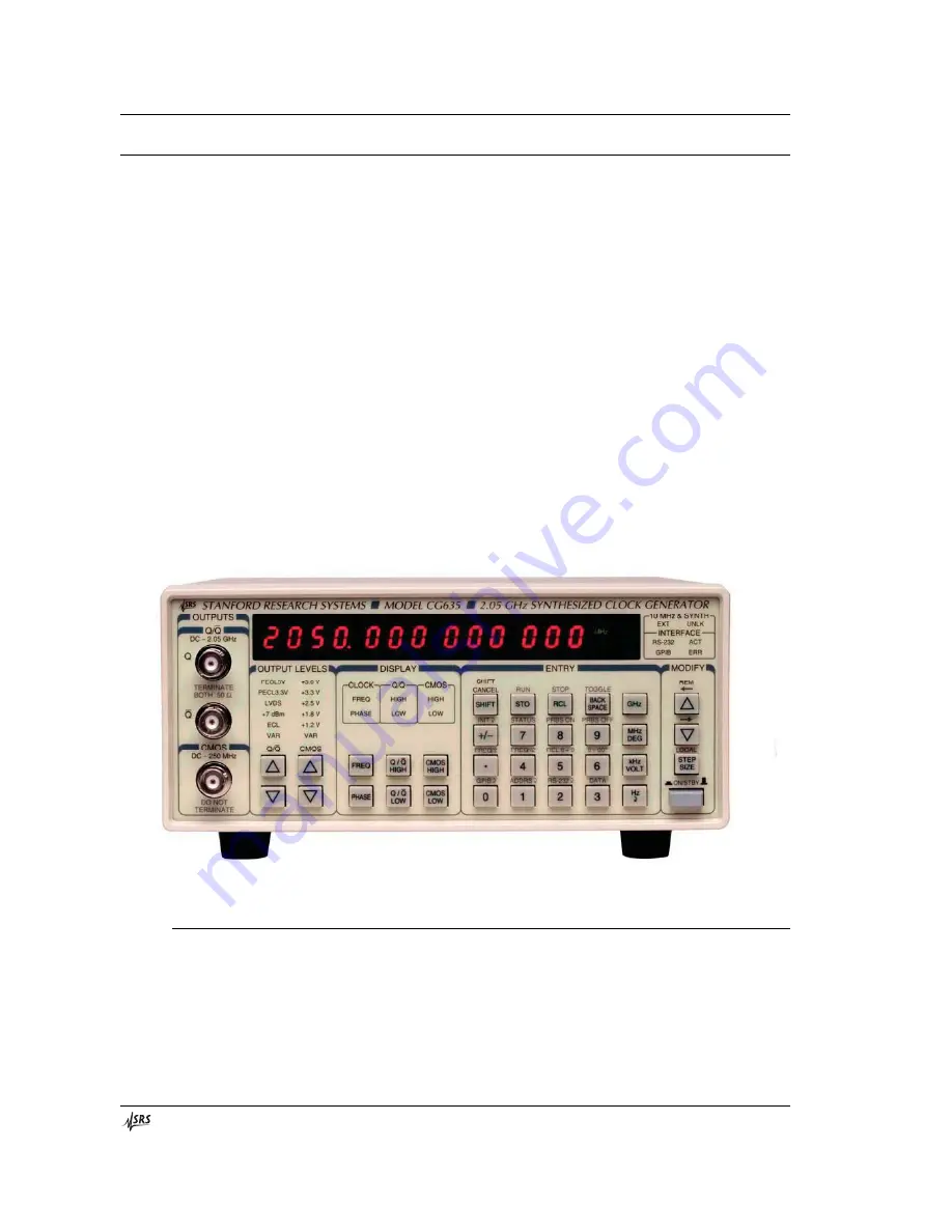
The front panel was designed to provide a simple, intuitive, user interface to all the
CG635 features (see Figure 1). The power switch is located in the lower right corner of
the front panel. Pushing the switch enables power to the instrument. Pushing the switch
again places the instrument in stand-by mode, where power is enabled only to optionally
installed timebases. Power to the main board is turned off in stand-by mode.
The front panel provides three output drivers for connecting the CG635 clock signals to
user applications via standard BNC cables. The two upper outputs are complementary,
high-speed, ECL compatible output drivers. The lower output is a CMOS output driver.
Keys on the front panel are divided into four sections to indicate their overall
functionality: OUTPUT LEVELS, DISPLAY, ENTRY, and MODIFY. Keys in the
OUTPUT LEVELS section modify the amplitude and offset of the clock signals provided
by the front panel output drivers. Keys in the DISPLAY section control what is shown in
the main display. The user can choose among six standard displays. Keys in the ENTRY
section are used for changing the currently displayed item to a specific value. This
section is also used to access secondary functions. Keys in the MODIFY section allow
the user to increment the currently displayed item by configurable steps.
Figure 1: The CG635 Front Panel
Outputs
Q and Q
¯
The CG635 front panel includes three BNC outputs. The upper two outputs, labeled Q
and Q
¯ , are high-speed drivers that operate from DC to 2.05 GHZ. The outputs provide the
user with fast, complementary voltages at the selected frequency, amplitude, and offset.


