Technical data and notes
10
GasLab Q2
G a s Q u a l i t y A n a l y z e r
Page 123 of 135
10.2.2 Extra additional markings
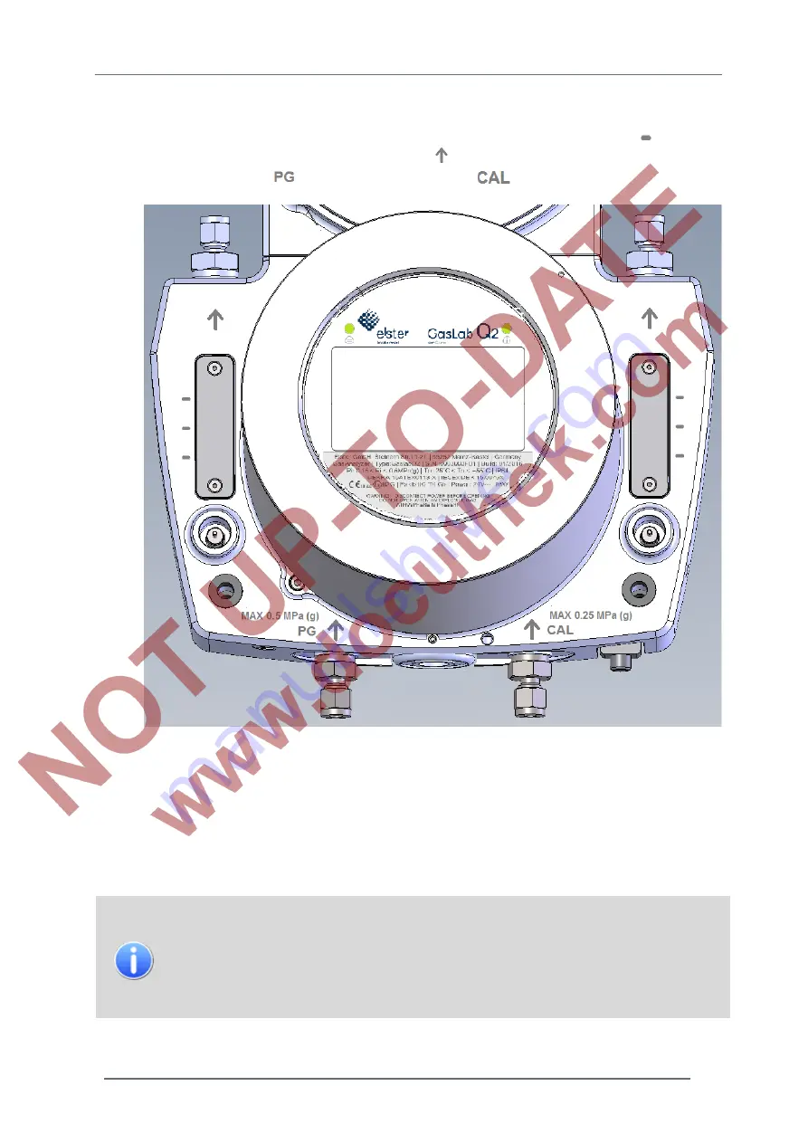
On the functional housing lower part of the device are the following markings: Level marks
for the gas
flows
bypass (left) and calibration process (right) Arrows
for the direction of the gas flows, maximum
inlet pressure of process gas
and calibration gas (cylinder)
Figure 10.4: Extra marks on the device
The ball of the left flowmeter begins to float at about 55 l / h. Marks indicate the flows of about 90 l / h
(bottom) 125 l / h (middle) and 160 l / h (at the top). On reaching the upper end, the maximum flow is set
to approximately 310 l / h.
The marks on the right flowmeter show the usual flows of about 30 l / h (below) approximately 40 l / h
(middle) and 60 l / h (top).
The flowmeters are only used for a rough estimation of the flow rate. If the ball is
within the three markings, sufficient flow is available for operation. A gas flow also
exists in the case of stationary balls. It is also possible to adjust the gas flow above
the maximum mark. Elster recommends to use an additional flow meter in cases
where the exact flow rate is critical. (After the setting process, this can be removed
again.)


