306
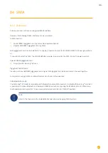
SMA
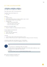
84.8
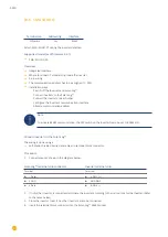
SMA - Sunny Central
Termination
Addressing
Interface
No
Yes
LAN
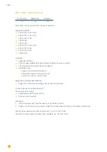
Select “SMA: Sunny Central CP“ for the device detection.
Supported models:
•
500 (CP-XT, CP-US, CP-JP)
•
630 (CP-XT, CP-US, CP-JP)
•
720 (CP-XT, CP-US)
•
750 (CP-US)
•
760 (CP-XT)
•
800 (CP-XT, CP-US, CP-JP)
•
850 (CP-XT, CP-US)
•
900 (CP-XT, CP-US)
•
1000 (CP-XT)
Overview
•
Integrated interface
•
Connect using network cable (patch cable) and Ethernet router or switch.
•
The communication address has to be assigned.
•
Installation steps
•
Assign the communication address.
•
Connect the inverters to the Solar-Log™.
•
Connect the inverters to each other.
Assign the communication address.
•
Assign the IP addresses according to the inverter‘s instructions.
Connect inverters and the Solar-Log™.
The wiring is done using a
•
network cable (patch cable) and the
•
Ethernet router or switch.
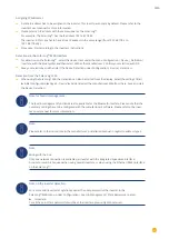
Procedure
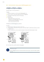
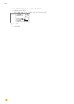
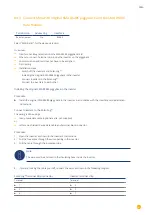
1. Connect the Solar-Log™ and the inverter to the router or switch.
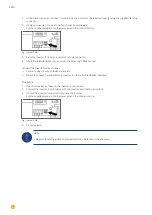
2. Assign an IP address to every inverter. Assign the IP addresses according to the inverter‘s instructions.
The first three number blocks like the Solar-Log™, e.g.
192.168.178
.49.
The fourth number block: an address that is available, e.g. 192.168.178.
50
.
Summary of Contents for Solar-Log
Page 1: ...1 Components Connection Manual V 4 2 3 Solar Log EN ...
Page 20: ...20 01 Inverter ...
Page 398: ...398 Appendix 113Appendix 113 1 SMA mixed wiring Fig SMA mixed wiring ...
Page 402: ...402 02 Meter ...
Page 444: ...444 03 Battery Systems ...
Page 456: ...456 sonnen Note Only one battery system can be connected to a Solar Log device ...
Page 463: ...463 04 Heating rods ...
Page 470: ...470 05 Heating pumps ...
Page 478: ...478 06 Sensors ...
Page 488: ...488 07 Pyranometer ...
Page 495: ...495 08 Smart Plug components ...
Page 502: ...502 09 Power Charging Stations ...

