Wall mounting
Required accessories
:
Wall mounting base (for compact version)
Order no. 1402-0529
Wall mounting base (for standard version)
Order no. 1402-0323
The base consists of two base components (base housing and frame), a terminal board for the
wiring, two wire connectors (for five conductors) for N and PE distribution as well as two clips to
hold the controller housing in place.
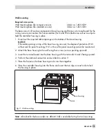
1. Knock out the required cable openings on the bottom of the base housing.
NOTICE
If the cable openings on top of the base housing are used, the degree of protection (IP 40
without seal for panel mounting, IP 41 with seal for panel mounting) cannot be maintained.
2. Attach the base housing to the wall using four screws (arrows pointing upward).
3. Insert the terminal board into the base housing with the terminals N and L facing upward.
4. Perform the electrical connection as described in section 11.
5. Place the frame on the base housing and screw them together.
6. Place the controller housing into the frame and insert the two clips on each side to lock
the housing in place.
Note:
A bracket for the base (order no. 8864-0168) is available for top-hat rail mounting.
EB 5610 EN
93
Installation
Fig. 9 · Wall mounting
Base housing
Frame
Summary of Contents for trovis 5600
Page 22: ...22 EB 5610 EN Setup settings B C D A A...
Page 124: ...124 EB 5610 EN...
Page 125: ...EB 5610 EN 125...
Page 126: ...126 EB 5610 EN Key number 1732...

