


11
Electrical connection
DANGER!
Risk of electric shock!
For electrical installation, you are required to observe the relevant electrotechnical regulations
of the country of use as well as the regulations of the local power suppliers. Make sure all electri-
cal connections are installed by trained and experienced personnel!
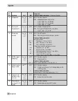
Notes on installing the electrical connections
4
Install the 230 V power supply lines and the signal lines separately! To increase noise immu-
nity, observe a minimum distance of 10 cm between the lines. Make sure the minimum dis-
tance is also observed when the lines are installed in a cabinet.
4
The lines for digital signals (bus lines) and analog signals (sensor lines, analog outputs) must
also be installed separately!
4
In plants with a high electromagnetic noise level, we recommend to use shielded cables for
the analog signal lines. Ground the shield at one side, either at the control cabinet inlet or
outlet, using the largest possible cross-section. Connect the central grounding point and the
PE grounding conductor with a cable
≥
10 mm² using the shortest route.
4
Inductances in the control cabinet, e.g. contactor coils, are to be equipped with suitable in-
terference suppressors (RC elements).
4
Control cabinet elements with high field strength, e.g. transformers or frequency converters,
should be shielded with separators providing a good ground connection.
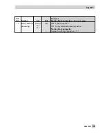
Overvoltage protection
4
If signal lines are installed outside buildings or over large distances, make sure appropriate
surge or overvoltage protection measures are taken. Such measures are indispensable for
bus lines!
4
The shield of signal lines installed outside buildings must have current conducting capacity
and must be grounded on both sides.
4
Surge diverters must be installed at the control cabinet inlet.
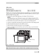
Connecting the controller
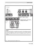
The controller is connected as illustrated in the wiring diagram (pages 96 and 97).
Open the housing to connect the cables. To connect the feeding cables, make holes at the
marked locations at the bottom of the rear part of the housing.
94
EB 5610 EN
Electrical connection
!
Summary of Contents for trovis 5600
Page 22: ...22 EB 5610 EN Setup settings B C D A A...
Page 124: ...124 EB 5610 EN...
Page 125: ...EB 5610 EN 125...
Page 126: ...126 EB 5610 EN Key number 1732...