9.1
Sensor failure
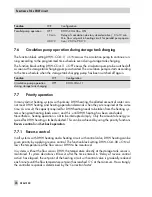
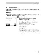
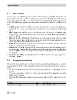
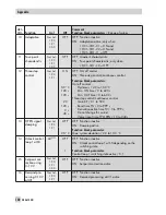
Sensor failures are indicated by 'Sensor failure' in the error list. For detailed information, exit
the error level and read the different temperature values in the information level: each sensor
icon displayed together with '–.–' instead of the measured temperature indicates a defective
sensor. The following list explains how the controller responds to the failure of the different sen-
sors.
4
Outdoor sensor:
When the outdoor sensor fails, the controller uses a flow temperature set
point of 50 °C or 'Max. flow temperature' when the 'Max. flow temperature' is lower than
50 °C.
4
Flow sensor:
When the flow sensor in the heating circuit is defective, the associated valve
moves to 30 % travel. DHW heating using such a sensor to measure the charging tempera-
ture is suspended.
4
Flow sensors in the DHW circuit:
When the flow sensor fails, the controller behaves as if the
flow sensor had not been configured. As soon as the control of the charging temperature be-
comes impossible, the associated valve is closed.
4
Return flow sensor:
When the return flow sensor fails, the controller continues operation
without return flow temperature limitation.
4
Room sensor:
When the room sensor fails, the controller uses the settings for operation with-
out room sensor. The controller, for example, switches from optimizing mode to reduced op-
eration; adaptation mode is canceled. The last determined heating characteristic remains
unchanged.
4
Top and bottom storage tank sensors:
When one of the two sensors fails, the storage tank is
no longer charged.
9.2
Temperature monitoring
When certain measured temperatures deviate from the set points by a defined amount, an error
message is generated. The following deviations lead to the 'Temperature monitoring' error mes-
sage:
4
The flow temperature deviates from the set point by at least 10.0 °C for longer than 30
minutes
4
The room temperature is at least 2.0 °C lower than the set point (flash adaptation active) for
longer than 30 minutes
4
The return flow temperature limitation has continuously taken effect for longer than 30 min-
utes
Functions
WE
Configuration
Temperature monitoring
OFF
HC1–CO5–19 = ON
90
EB 5610 EN
Operational faults
Summary of Contents for trovis 5600
Page 22: ...22 EB 5610 EN Setup settings B C D A A...
Page 124: ...124 EB 5610 EN...
Page 125: ...EB 5610 EN 125...
Page 126: ...126 EB 5610 EN Key number 1732...

