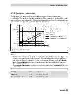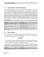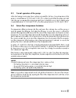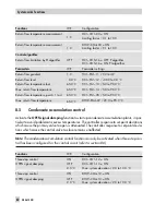
latest, the storage tank charging pump P3 is switched on.
If a storage tank thermostat is used, the storage tank charging pump P3 is switched on when the
temperature T = Charging temperature – 5 °C is reached at the flow sensor S1.
Note:
The storage tank charging temperatures are adjusted instead of the storage tank temper-
atures in the menu item for DHW set points when a storage tank thermostat is used.
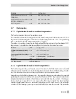
When the flow sensor S6 is activated, the set point in the heat exchanger circuit is influenced by
the system deviation in the storage tank charging circuit upon activation of the storage tank
charging pump P3: if the temperature measured at flow sensor S6 is lower than the desired
charging temperature, the set point in the heat exchanger circuit is increased in steps of 1 °C.
When the set point in the heat exchanger charging circuit reaches the 'Max. charging tempera-
ture', the set point is no longer increased. An error message 'Max. charging temperature
reached' is generated.
Note:
The set point in the heat exchanger circuit which is valid at the end of the charging cycle
will be used again at the beginning of the next cycle.
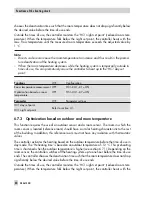
If times-of-use have been set for DHW heating, 'DHW day set point' applies during these
times-of-use.
Outside the times-of-use, the 'DHW night set point' is used. This does not apply when a storage
tank thermostat is used.
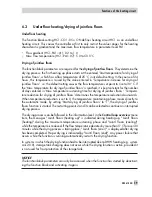
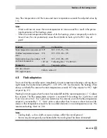
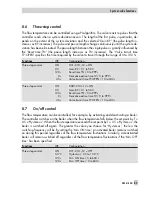
Time-controlled switchover of storage tank sensors
The function block setting DHW–CO4–19 = ON determines that the storage tank sensor S7 is
used for day mode in the DHW circuit and that the storage tank sensor S8 is used for night
mode. As a result, different storage tank volumes can be kept at a constant temperature accord-
ing to a time schedule, and also at different temperatures if the 'DHW day set point' and 'DHW
night set point' differ from one another.
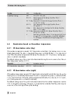
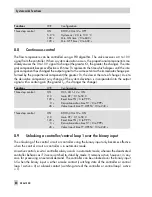
Stop storage tank charging
The controller stops charging the storage tank when the water temperature measured at sen-
sor S8 has reached the temperature T = 'DHW day set point' + 'Hysteresis'. To avoid accumu-
lated heat, the heat exchanger charging pump continues to run for the time entered in 'Lag time
for storage tank charging pump' when the valve closes. The storage tank charging pump P3 is
switched off approx. ten seconds after the lag time of the heat exchanger charging pump.
EB 5610 EN
71
Functions of the DHW circuit
Summary of Contents for trovis 5600
Page 22: ...22 EB 5610 EN Setup settings B C D A A...
Page 124: ...124 EB 5610 EN...
Page 125: ...EB 5610 EN 125...
Page 126: ...126 EB 5610 EN Key number 1732...

