109
K2 K1 command
0
0
stop
0
1
forward
1
0
stop
1
1
reverse
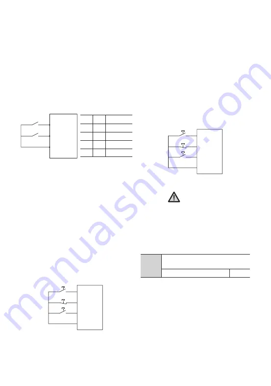
Fig. F7-3 2-wire Control Mode 2
Fig. F7-5 3-wire control mode 2
Fig. F7-4 3-wire Control Mode 1
1: 2-wire control mode 2
Xm: forward command (FWD); Xn: reverse
command (REV). Xm and Xn are two random
terminals among X1-X8 defined as FWD and
REV function respectively. In this control
mode, K1 is switch of run and stop, K2 is for
direction switching.
3: 3-wire control mode 1
Xm: forward command (FWD); Xn: reverse
command (REV); Xx: stop command. Xm,
Xn and Xx are 3 random terminals among
X1-X8 defined as FWD, REV and 3-wire
control function respectively. K1 and K2 are
invalid without connecting of K3. After K3 is
connected, K1 is triggered, and the VFD runs
forward; disconnect K3, then the VFD will
stop.
2: 3-wire control mode 2
Xm: operating command; Xn: running
direction; Xx: stop command. Xm. Xn. Xx are
3 random terminals among X1-X8 defined as
FWD, REV and 3-wire control function. K1 and
K2 are invalid without connection of K3. After
K3 is connected, trigger K1, and the VFD runs
forward; triggering K2 alone is invalid; trigger
K2 after K1, the driver will switch its running
direction; disconnect K3, the driver will stop.
Notice
When forward running with 3-wire control
mode 2, the VFD can reverse steadily only
if the REV terminal is normally closed, once
disconnected of the terminal, the driver
will runs forward.
,
9N '8%
9O 3&7
$0.
,
,
9N '8%
9Y
9O 3&7
$0.
,
,
,
9N '8%
9Y
9O 3&7
$0.
,
,
4.2 Detailed Function Description
This function code is used to setting the
frequency modifying rate of UP/DOWN
terminal, i.e. the changed value of frequency
when short-circuit UP/DOWN terminal with
COM for one second.
When F0.18=1 (high frequency mode), the
upper limit value of this function code is
500.0Hz/s.
F7.12
UP/DOWN terminal frequency
modifying rate
0.01 ~ 50.00Hz/S
1.00
Summary of Contents for SKI600
Page 3: ......
Page 4: ...88888 Operating Instruction Manual High performance Vector Inverter ...
Page 179: ......
Page 180: ......


