


1041901, R
EV
. 00
P
AGE
20 - R
EPAIR
K
ITS
M
ILLENNIUM
S
ERVICE
& T
ECHNICAL
I
NFORMATION
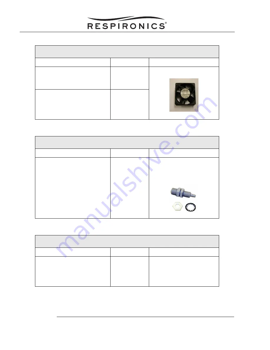
C
OOLING
F
AN
K
ITS
Concentrator Model #
Kit #
Included in Kit
•
M10600/M10605 Concentrators
•
Enhanced M10600/M10605
Concentrators
1014673
•
Cooling fan
•
H600/H605 Concentrators
•
M600/M605 Concentrators
•
Enhanced M600/M605
Concentrators
360-9100-15
DISS O
UTLET
F
ITTING
K
IT
Concentrator Model #
Kit #
Included in Kit
•
All Millennium Concentrators
H628
•
DISS outlet fitting
•
1/2” lock washer
•
1/2” - 13 jam nut (nylon)
E
LBOW
/H
OSE
K
IT
Concentrator Model #
Kit #
Included in Kit
•
All Millennium Concentrators
1006510
•
Fitting, 3/8” hose barb,
elbow, nylon
•
Hose braided (1 ft.)
•
One eared clamp